4/7
C 200
Control panel
GB 03292 - Edition 03 - March 12
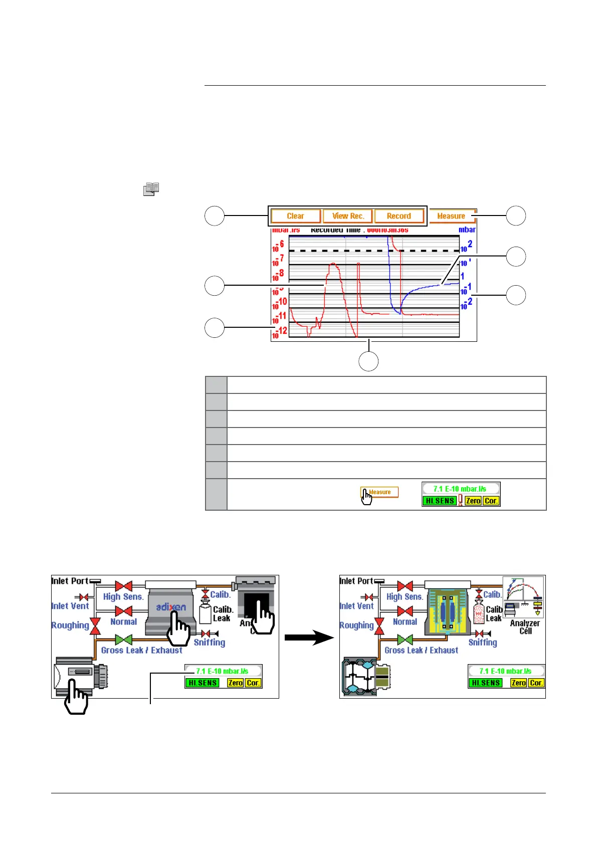
Graphic display
C 300
Display used to facilitate the tests requiring a high precision, by
showing the measured signal and its evolution.
1 Delete/visualisate/record graph
2 Tracer gas signal display (in red)
3 Tracer gas signal scale (in red)
4 Time scale
5 Inlet pressure scale (in blue)
6 Inlet pressure display (in blue)
7
Measure/masking display:
—>
4
2
3
5
6
Vacuum circuit Display used to follow the valves state during a test and so to have a
better knowledge of the detector functioning.
Measured
signal digital
display
The vacuum circuit varies according to the detector state:
n green: valve opened
n red: valve closed.
It is not possible to control valves.
1
7
adixen Vacuum Products - ASM 310 Operating instructions