10.5.4.1 Alignment DCM
The alignment DCM (Direction Cosine Matrix) is used to represent an alignment offset of GNSS Compass from
its standard alignment. A DCM is used rather than Euler angles for accuracy reasons. To convert Euler angles
to DCM, use the formula below with angles in radians.
DCM[0][0] = cos(heading) * cos(pitch)
DCM[0][1] = sin(heading) * cos(pitch)
DCM[0][2] = -sin(pitch)
DCM[1][0] = -sin(heading) * cos(roll) + cos(heading) * sin(pitch) * sin(roll)
DCM[1][1] = cos(heading) * cos(roll) + sin(heading) * sin(pitch) * sin(roll)
DCM[1][2] = cos(pitch) * sin(roll)
DCM[2][0] = sin(heading) * sin(roll) + cos(heading) * sin(pitch) * cos(roll)
DCM[2][1] = -cos(heading) * sin(roll) + sin(heading) * sin(pitch) * cos(roll)
DCM[2][2] = cos(pitch) * cos(roll)
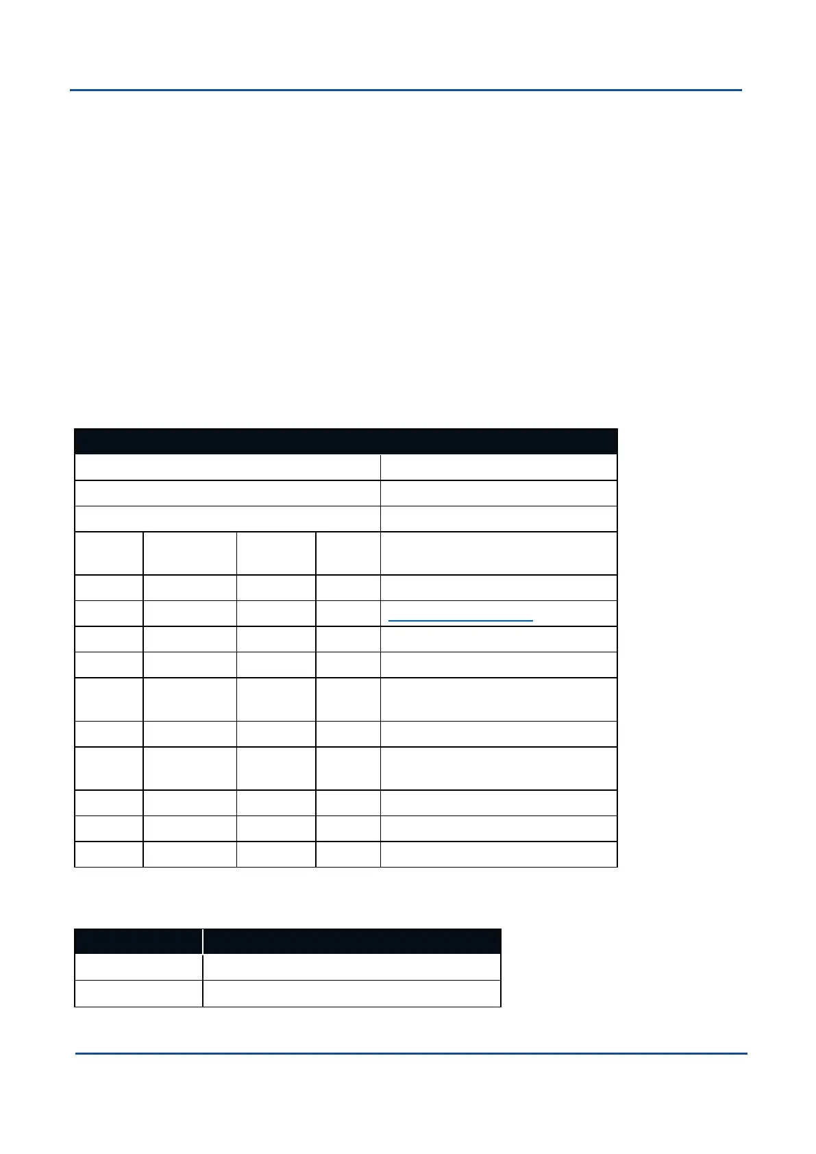
10.5.5 Filter Options Packet
Filter Options Packet
Packet ID 186
Length 17
Read / Write Read / Write
Field # Bytes Off-
set
Data
Type
Size Description
1 0 u8 1 Permanent
2 1 u8 1 10.5.5.1 Vehicle Types
3 2 u8 1 Internal GNSS enabled (boolean)
4 3 u8 1 Reserved (set to zero)
5 4 u8 1 Atmospheric altitude enabled
(boolean)
6 5 u8 1 Velocity heading enabled (boolean)
7 6 u8 1 Reversing detection enabled
(boolean)
8 7 u8 1 Motion analysis enabled (boolean)
9 8 u8 1 Reserved (set to zero)
10 9 8 Reserved (set to zero)
Table 103: Filter Options Packet
10.5.5.1 Vehicle Types
Value Description
0 Unlimited
1 Bicycle or Motorcycle
v2.0 Page 114 04 Nov 2021
GNSS Compass Reference Manual • Advanced Navigation Packet Protocol