enhanced position and velocity solution that can withstand GNSS drop outs.
11.2 The Sensor Co-ordinate Frame
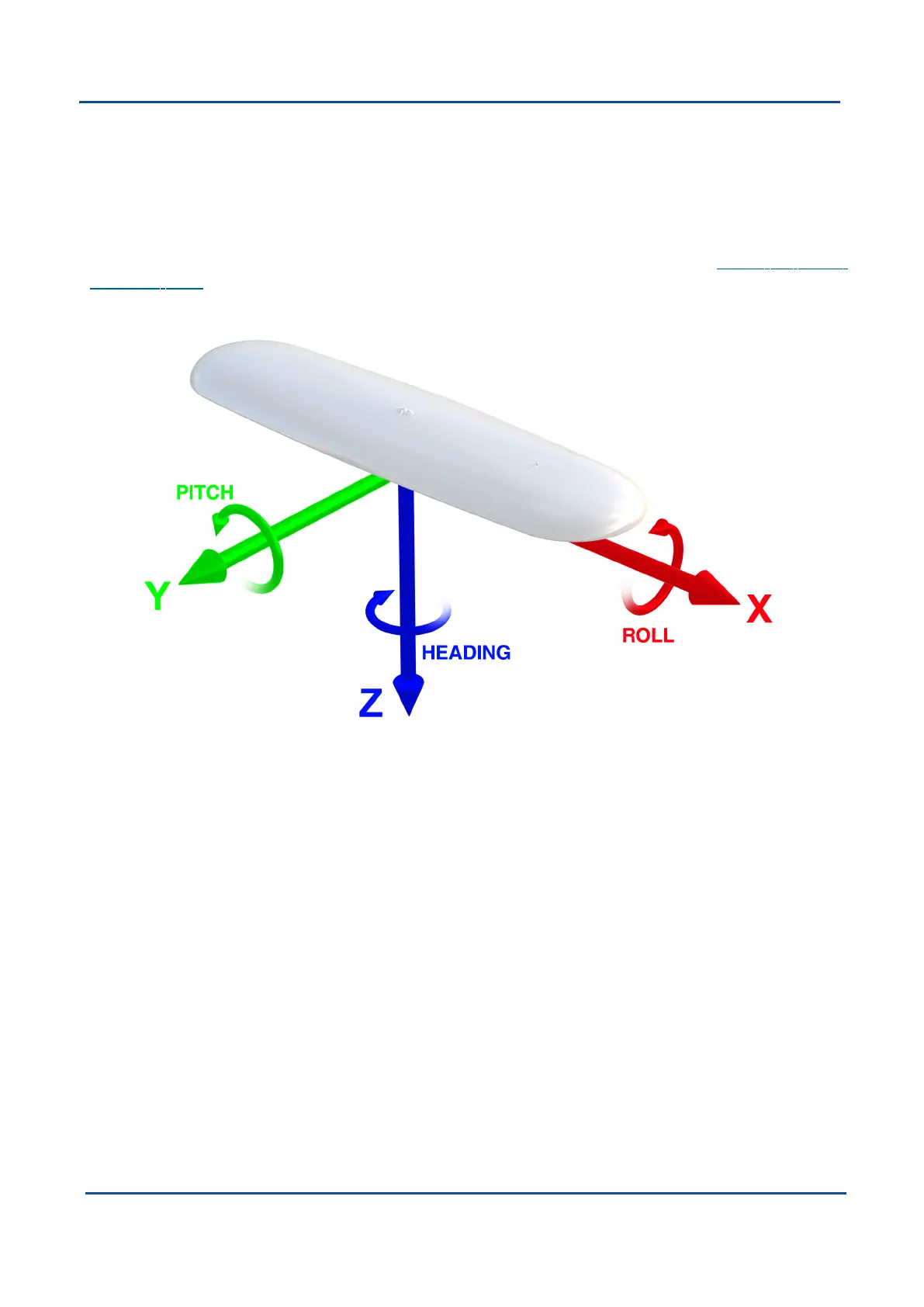
Inertial sensors have 3 different axes: X, Y and Z and these determine the references around which angles and
accelerations are measured. It is very important to align these axes correctly in installation, otherwise the
system won't work correctly. These axes are marked on the top of the device as shown in Figure 53: GNSS
Compass Axes below with the X axis pointing in the direction of the connectors, the Z axis pointing down
through the base of the unit and the Y axis pointing off to the right.
Figure 53: GNSS Compass Axes
When installed in an application the X axis should be aligned such that it points forwards and the Z axis aligned
so that it points down when the system is level. A good way to remember the sensor axes is the right hand rule,
which is visualised in the figure below.
v2.0 Page 122 04 Nov 2021
GNSS Compass Reference Manual • GNSS Compass Reference Information