OPTION 11 FAST PULSE AND HIGH POWER
Annex-B-11
Pulse modulation on/off ratio
C5805
UUT
RF
OUTPUT
Spectrum analyzer
RF INPUT
PULSE
INPUT
OUTPUT
Function generator
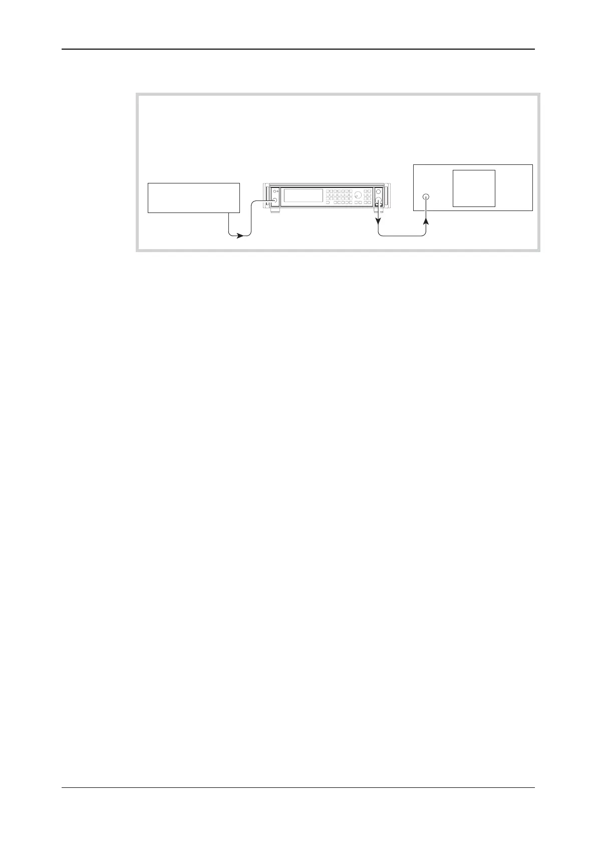
Fig. B-8 Pulse modulation on/off ratio test set-up
Test procedure
(1) Press CAL on the spectrum analyzer.
(2) Connect the test equipment as shown in Fig. B-8.
(3) On the UUT set:
[CARR FREQ] 100 [kHz]
[RF LEVEL] 0 [dB]
[MENU] 22 ENTER
The UUT enters the Pulse Modulation menu
Select 1 (To enable Ext Pulse Mod.)
[MOD] then [MOD] then [MOD] again (To select Pulse Mod EXT ON)
[SOURCE ON/OFF] (To enable modulation source)
[MOD ON/OFF] (To enable modulation)
(4) Set the function generator to provide +5 V DC. The RF output is now enabled.
(5) Tune the spectrum analyzer to the same frequency as the signal generator.
(6) Press PEAK FIND on the spectrum analyzer and note the output level.
(7) Apply a short circuit to the PULSE INPUT socket.
(8) Again note the output level measured by the spectrum analyzer.
(9) The difference between the levels recorded in (6) and (8) is the pulse mod on/off ratio.
Check that the ratio is within specification using Table B-15.
(10) Repeat (5) to (9) for each of the frequencies shown in Table B-15.



 To Next Page