OPTION 11 FAST PULSE AND HIGH POWER
Annex-B-12
Pulse modulation rise and fall time
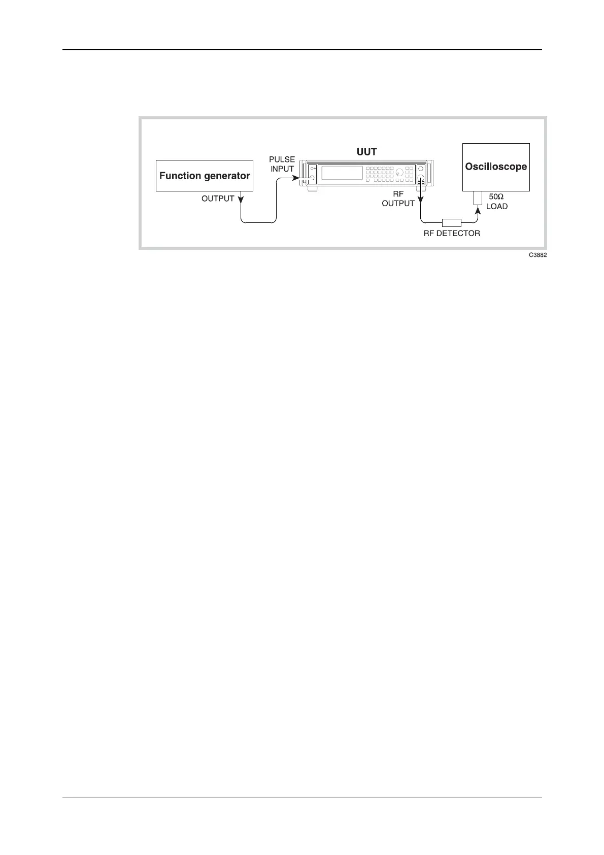
Fig. B-9 Pulse modulation rise and fall time test set-up
Test procedure
(1) Connect the test equipment as shown in Fig. B-9.
(2) On the UUT set:
[CARR FREQ] 1 [GHz]
[RF LEVEL] +7 [dB]
[MENU] 22 ENTER
The UUT enters the Pulse Modulation menu
Select 1 (To enable Ext Pulse Mod.)
[MOD] then [MOD] then [MOD] again (To select Pulse Mod EXT ON)
[SOURCE ON/OFF] (To enable modulation source)
[MOD ON/OFF] (To enable modulation)
(3) Set the function generator to produce 100 kHz, 0 V to +5 V square wave.
(4) Adjust the oscilloscope controls such that the rise time of the envelope can be measured.
(5) Measure the rise time between the 10% to 90% points checking that it is within the
specification shown in Table B-16.
(6) Repeat (4) to (5) for the fall time of the envelope.



 To Next Page