64
• If the insertion loss is still not acceptable, replace both test jumpers and repeat steps 1-13.
14. If the insertion loss is acceptable, disconnect the transmit and receive jumpers at the adapter.
15. Move the OPM and OLS to opposite ends of the link to be tested.
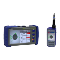
OPM Operation - Testing Multimode/Single-mode Fibers
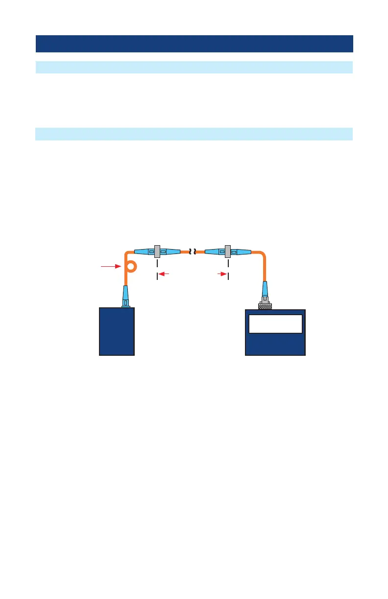
16. Connect the free ends of the transmit and receive jumpers to the link under test.
Note: Clean jumper end that connects to patch panel prior to every test.
17. The OPM will measure and display the insertion loss of the link under test.
18. Press the Save key on the OPM to save the displayed measurement.
19. Repeat steps 16-18 for all links to be tested at the current wavelength(s).
Step II - Verify Test Jumpers
Step III - Measure Link Insertion Loss
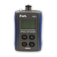
OPMOLS
2.00 dB
Link under test
Transmit jumper
Receive jumper
Patch panelPatch panel
loop (SM) or
mandrel (MM)