62
Bi-directional Analysis Operation
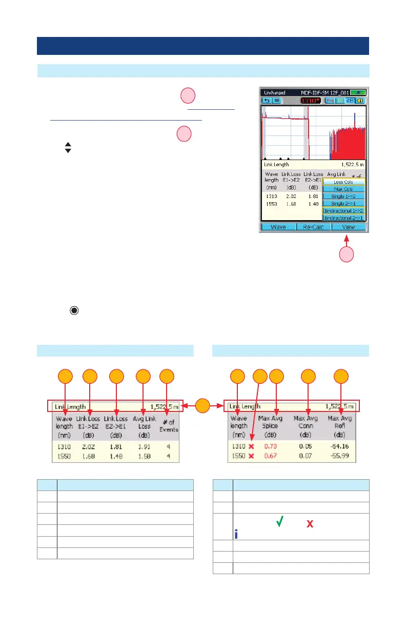
1. Press Wave to display the Wave menu
A
and select the
desired wavelength to be displayed (see “Wavelength
Selection Menu In OTDR Pages” on page 45 for details).
2. Press View to display the View menu
A
.
3. Use arrows to make selection as follows:
• Select Loss Cols option to display the column set # 1, which
includes:
– Link Loss End1 -> End2
– Link Loss End2 -> End1
– Average Link Loss data
• Select Max Cols option to display the column set # 2, which
includes:
– Max Average Splice Loss between the directions,
– Max Average Connector Loss between the directions,
– Max Average Reectance between the directions data.
4. Press key to conrm selection.
5. The Summary page will display test results for the selected Column Set option as shown
below.
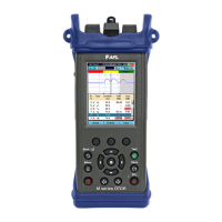
How to Switch Column Sets in Summary Page (Bi-directional View)
Column Set - “Loss Cols” Column Set - “Max Cols”
Ref. Description
1 This row displays Link Length
2 Test Wavelength(s)
3 Link Loss End1 -> End2 (dB)
4 Link Loss End2 -> End1 (dB)
5 Average Link Loss data (dB)
6 Number of Events
Ref. Description
1 This row displays Link Length
2 Test Wavelength(s)
2
Status eld:
- Pass, - Fail,
- Information only
4 Max Average Splice Loss (dB)
5 Max Average Connector Loss (dB)
6 Max Average Reectance (dB)
3 3 42 2
1
65 64 5
A