5
Hardware Overview
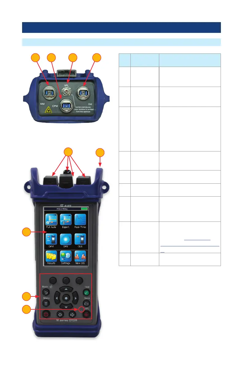
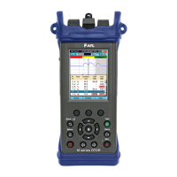
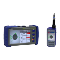
Controls, Indicators, and Ports
Ref Control/
Feature
Description
1 MM port
This is a CLASS I LASER
output - 850/1300 nm
multimode OTDR port.
2 SM port
This is a CLASS I LASER
output - 1310/1550 nm
single-mode OTDR port.
3 VFL port
This is a CLASS II LASER
output. Do not stare into
beam.
The VFL (visual fault locator)
port is a 650 nm (red) laser.
Used for short-range fault-
location.
4 OPM port Optical Power Meter port.
Used for power (dBm, W) or
loss (dB) measurements.
5 Dust cap Used to protect optical ports
from dust/damage.
6 Boot A proven shock-absorbing
rubber boot.
7 Touchscreen
display
Contains on-screen controls
and menus. Used to show
setup menus, test results, and
saved test data information.
8 Function
keys
These are the hard function
keys and soft function keys.
See section “Front Panel
Keys and Functions” on page
7 for details.
9 VFL
Indicator
This indicator Illuminates
when the VFL port is active.
Top Panel View
Front Panel View
2341
5
6
7
8
9