93
SETUP
VIRTUAL TERMINAL
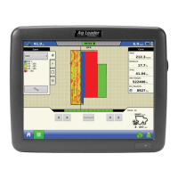
Pressing the Diagnostics button on the Devices
screen brings up the ISO Node Diagnostics screen
which shows the following information.
• SPN
“Suspect Parameter Number” = Error Number
• FMI
“Fault Mode Indicator” = Error State.
• OC
“Occurrence Count”
• DTC
Diagnostic Trouble Code
This is a combination of the SPN and the FMI (for
example 522102.12).
Cross-reference DTC in equipment manufacturer’s operator manual for description of error.
TASK CONTROLLER
With the addition of Task Controller, a code component within the VT, the system can provide support
for functions such as data logging and variable rate application, if the ECU supports TC.
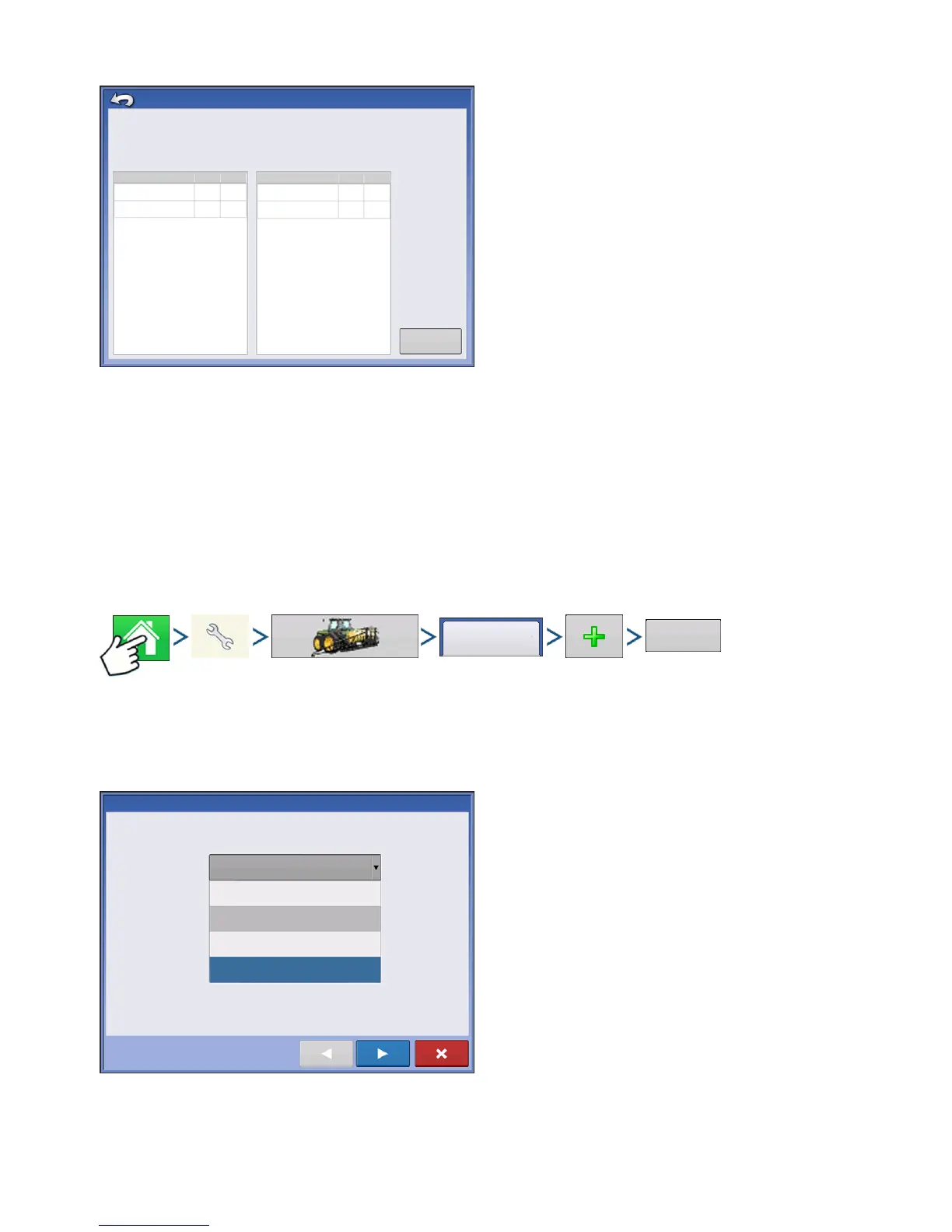
CONFIGURATION SETUP
Press: Home button > Setup (wrench) button > Configuration (tractor) button > Configuration tab > Plus
(+) button > Application button.
Configuration setup is the same as Liquid Rate Control and Granular Rate Control (
“Create Configuration”
on page 217) until Select Controller step. Select ISOBUS controller as follows:
Select ISOBUS as the device
ISO Node Diagnostics
ECU ID:
Software ID:
FMA_R 0.9 2006-05-23
Active Errors:
SPN
FMI
OC
Previously Active Errors:
SPN
FMI
OC
522102
12
1
523666
3
2
522102
523666
1
2
3
Clear Previously
Active Errors
12
Configuration
Application
Controller Setup Wizard: Device
Select Controller or Flow Meter
Device
ISOBUS
DirectCommand
Serial Controller
Flow Meter
ISOBUS
 Loading...