295
APPLICATION
STRIP TILL
• Max Metering Speed
Setting determines the maximum RPM of the metering shaft that controls product distribution to the
application point. This setting is used when controlling a granular strip-till toolbar.
Strip Till Control: PWM Control Valve
• PWM Frequency
The frequency that the PWM control valve is pulsed at.
Settings can be found from the manufacturer of the
valve. Typical settings range from 100-125 Hz. The
default setting is 100.
• PWM Gain
Determines how aggressively the control valve responds
when making rate changes. The higher the value the
more aggressive the system response is. The default
setting is 100.
• Zero Flow Offset
Represents the maximum duty cycle that is sent to the
control valve without producing any hydraulic flow from
the PWM valve. Using too high of a Zero RPM Offset value can cause the conveyor to not properly shut off.
See the PWM valve manufacturer information for recommended settings. The default setting is 30.
• Allowable Error
Determines the percent of error that is allowed prior to the product control system making any flow rate
changes. 2% - 3% is the normal dead band setting range.
- Too low of a setting value can cause the product control system to continually hunt for the target
application rate.
- Too high of a setting will cause excessive product application error.
• Shaft Speed Calibration
Calibration number representing the pulses that equal one revolution of the rate control metering system.
• Max Metering Speed
Setting determines the maximum RPM of the metering shaft that controls product distribution to the
application point. This setting is used when controlling a granular strip-till toolbar.
Linear Actuator/Clutch Settings
Note: When using Linear Actuator Control, the system requires the Control Valve Configuration on all three
channels to be set the same.
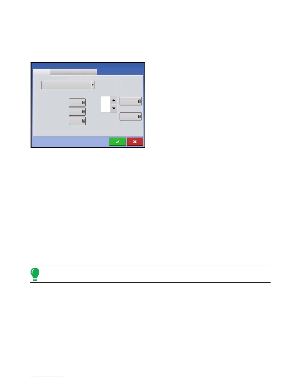
Strip Till Control
Channel 1
Channel 2
Channel 3
Auxiliary
Control Valve Configuration
PWM
PWM Frequency
100
PWM Gain
100
Zero Flow Offset
30
Allowable
Error
2 %
Shaft Speed
Calibration
180 pls/rev
Max Metering
Speed
100 rpm
 Loading...