225
APPLICATION
LIQUID RATE CONTROL
After specifying Fence Row Nozzle
settings at the Auxiliary Input Assignment
screen, the Fence Row Nozzle
Indicators (A), which are shaped like
triangles, appear on either side of the
sections behind the vehicle icon.
Notes:
If a switch is selected as a Left or Right Fence Row Nozzle, the system sends power out of Boom Pin 11
for the left fence row, and Boom Pin 12 for the right fence row.
The boom sections next to the fence row nozzles must be turned on before the fence row nozzle can be
turned on.
LOAD CONFIGURATION
Press: Select Event button.
Select a Season, Grower, Farm, and
Field on the Management Selection
screen.
For more information, see
“Setup Event” on page 49.
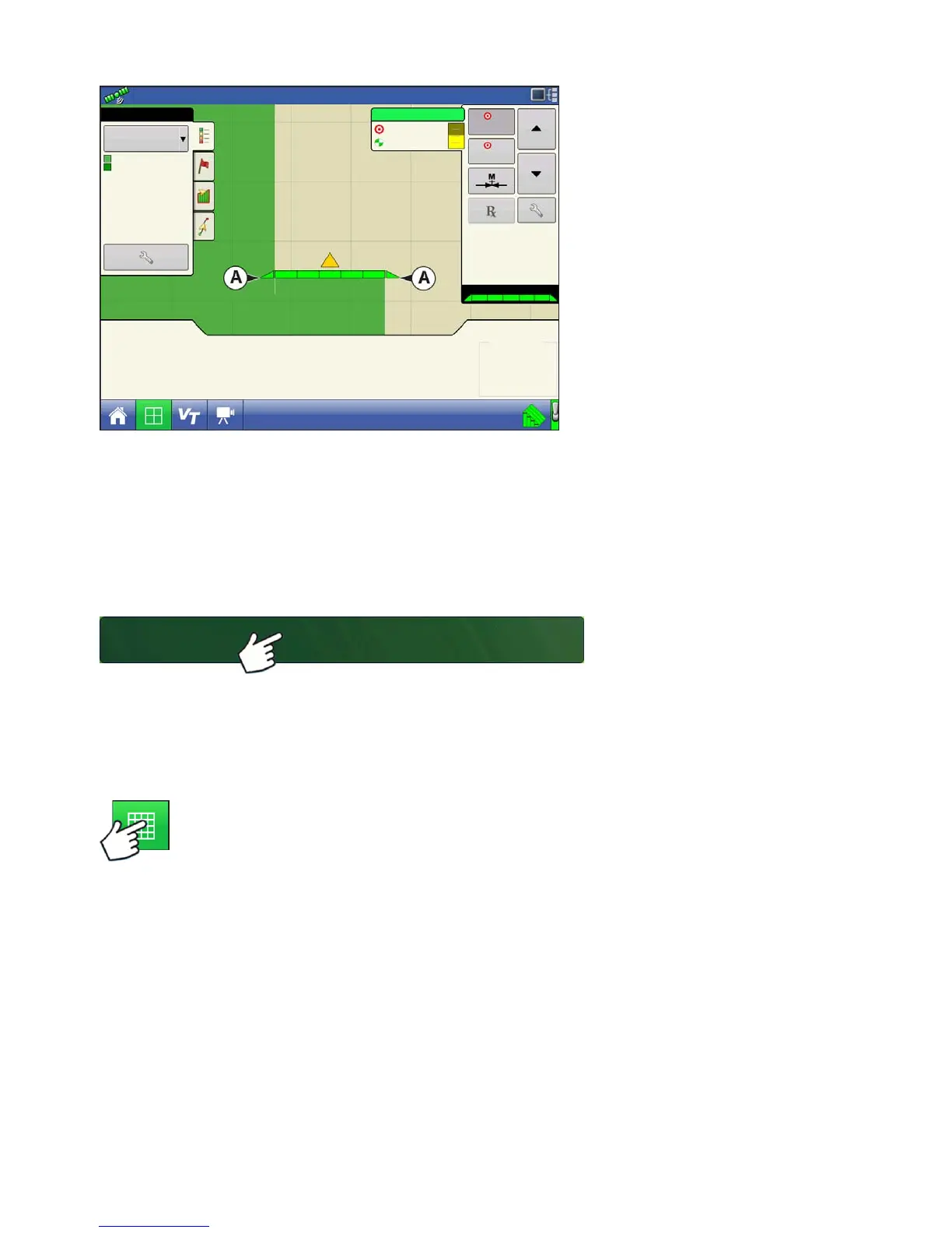
RUN CONFIGURATION
Once a configuration has been completed, the Map View button appears at the bottom of the
Home screen. Press the Map View button to see the Map screen. The map below is displayed
in Zoom to Detail view.
80 ft
47
43
41
Pressure (PSI)
630 gal
544.8 lb/min
150
150
lb/ac
2
1
130
150
15.0 mph
38.4 ac
N
Flow:
Container:
100%
Main:
Agitation:
Auxiliary:
Coverage
Overlap
Coverage
NH3
Select Event
 Loading...