143
GUIDANCE
ONTRAC2+
5. When the vehicle's draw bar reaches the flag, stop the vehicle, place it in park, turn off the AutoSteer
system, and exit the vehicle.
6. Check to see if the center of the draw bar is over the flag.
7. If the flag is exactly beneath the center of the draw bar, no adjustment is needed.
8. If not, use a plumb bob to mark the spot directly beneath the draw bar, and then measure the distance
between that spot and the flag.
9. Calculate the Offset Error by dividing the measured distance by 2. (The measurement is divided by
two because taking the measurements driving in opposite directions doubles any error.)
10. Observe the offset of the error from the rear of the vehicle. Take note of whether the 2nd point is to
the left or right of the original flag. If the error is to the right of the original point, the existing Antenna
Lateral Offset must be adjusted to the left by the calculated Offset Error (and vice versa).
11. Go to the Edit Vehicle > Antenna Lateral Offset screen and edit the Antenna Lateral Offset value by
adjusting the existing value and/or changing the offset from Left to Right.
Note: This adjustment may require you to select a different left/right offset direction.
12. Repeat the procedure to ensure that the lateral offset is now correct. If the offset is consistently within
1 to 2 inches (2 to 5 cm) it is correct.
Example:
a. The calculated Offset Error is 2 inches (5 cm) [4 inches (10 cm) / 2 = 2 inches (5cm).
b. The offset direction is to the right.
c. We need to move the point to the left and the original offset was to the right, so we subtract. [5
inches (13 cm) - 2 inches (5 cm) = 3 inches (8 cm)].
d. Enter 3 inches (8 cm) as the Antenna Lateral Offset.
e. The offset direction (Left or Right) does not need to be changed in this case.
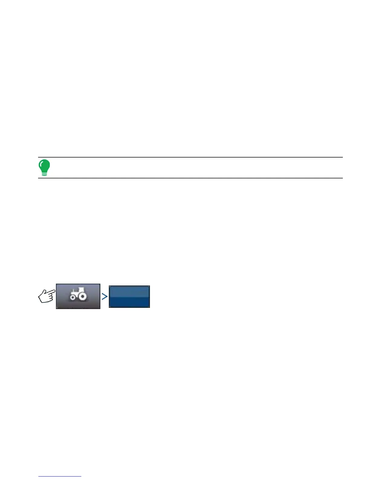
STEERING ADJUST
Press: Vehicle button > Steering Adjust button
You can change the response of the following items by using the slider bar.
Steering Response — controls the oscillations of the vehicle when it is on the desired path.
Cross-Track Error — adjusts how aggressively the vehicle reacts to changes in cross-track error.
Line Acquisition — determines how aggressively the system steers onto the desired steering path. The
ideal setting allows the system to take the shortest route without excessively sharp or sudden
movements of the vehicle.
Minimum Motor Output — defines the minimum power needed for the MDU to turn the steering wheel.
The Steering Adjust screen enables you to improve your vehicle AutoSteering performance. You can
change the response rate of the selected item with the screen slide bar:
• The turtle icon indicates slower (smooth) response.
• The rabbit icon indicates faster (aggressive) response.
Vehicle
Steering
Adjust
 Loading...