Home
Agilent Technologies
Security Sensors
1260
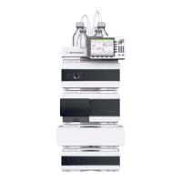
Agilent Technologies 1260 User Manual
5
of 1
of 1 rating
282 pages
Give review
Manual
Specs
To Next Page
To Next Page
To Previous Page
To Previous Page
Loading...
Agilent 1260 Inf
inity DA
D and MWD User Manual
29
Introduction
1
Setting the 8-bit Co
nfiguration Switch
One star
t bit and one st
op bit are always used (not selectable).
P
er default, the module will tur
n into 19200 baud, 8 dat
a bit with no parity.
Ta
b
l
e
9
Parity Settings (without on-board LAN)
Switches
Parity
78
0
0
No Parity
1
0
Odd Parity
11
E
v
e
n
P
a
r
i
t
y
28
30
Table of Contents
Table of Contents
5
1 Introduction
9
Introduction to the Detector
10
Optical System
11
Optical System
12
Early Maintenance Feedback (EMF)
14
Instrument Layout
15
Electrical Connections
16
Electrical Connections
17
Interfaces
18
Interfaces
19
Interfaces Overview
20
Setting the 8-Bit Configuration Switch
24
Setting the 8-Bit Configuration Switch
25
Communication Settings for RS-232C
28
Special Settings
30
2 Site Requirements and Specifications
33
Site Requirements
34
Physical Specifications
37
Performance Specifications
38
Specifications
38
Specification Conditions
41
3 Installing the Module
43
Unpacking the Detector
44
Damaged Packaging
44
Delivery Checklist
45
Optimizing the Stack Configuration
46
Two Stack Configuration
48
Installing the Detector
50
Flow Connections to the Detector
53
Setting up the LAN Access
56
4 LAN Configuration
57
What You Have to Do First
58
TCP/IP Parameter Configuration
59
Configuration Switch
60
Initialization Mode Selection
61
Link Configuration Selection
65
Automatic Configuration with Bootp
66
About Agilent Bootp Service
66
How Bootp Service Works
67
Situation: Cannot Establish LAN Communication
67
Installation of Bootp Service
68
Two Methods to Determine the MAC Address
70
Assigning IP Addresses Using the Agilent Bootp Service
71
Changing the IP Address of an Instrument Using the Agilent Bootp Service
74
Storing the Settings Permanently with Bootp
76
Manual Configuration
77
With Telnet
78
With the Instant Pilot (G4208A)
82
5 Using the Detector
83
Setting up an Analysis
84
Before Using the System
84
Requirements and Conditions
86
Optimization of the System
89
Preparing the HPLC System
90
Running the Sample and Verifying the Results
99
Special Settings of the Detector
100
Control Settings
100
Configuration Settings
101
Online Spectra (DAD Only)
102
Run Recovery Settings
103
Automated Run Recovery in Case of Temporary Communication Failures
104
Manual Run Recovery in Case of Permanent Communication Failures
106
Analog Output Settings
107
Spectrum Settings (DAD Only)
108
Peakwidth Settings
110
Slit Settings
112
Margin for Negative Absorbance Settings
113
Optimizing the Detector
113
Special Setups with Multiple DAD-Mwds
114
Two Detectors of same Type (E.g. G1315C/D and G1315C/D)
114
Two Detectors of Similar Type (E.g. G1315C/D and G1315A/B)
114
6 How to Optimize the Detector
115
Introduction
116
Optimization Overview
117
Optimizing for Sensitivity, Selectivity, Linearity and Dispersion
119
Flow Cell Path Length
119
Peak Width (Response Time)
121
Sample and Reference Wavelength and Bandwidth
123
Slit Width
126
Optimizing Spectral Acquisition (DAD Only)
128
Margin for Negative Absorbance
128
Optimizing Selectivity
129
Quantifying Coeluting Peaks by Peak Suppression
129
Ratio Qualifiers for Selective Detection of Compound Classes
131
7 Troubleshooting and Diagnostics
133
Overview of the Module's Indicators and Test Functions
134
Status Indicators
135
Power Supply Indicator
135
Module Status Indicator
136
User Interfaces
137
Agilent Lab Advisor Software
138
8 Error Information
139
What Are Error Messages
141
General Error Messages
142
Timeout
142
Shut-Down
143
Remote Timeout
143
Synchronization Lost
144
Leak Sensor Short
144
Leak Sensor Open
145
Compensation Sensor Open
145
Compensation Sensor Short
146
Fan Failed
146
Leak
147
Additional Information
148
Open Cover
149
Cover Violation
149
Detector Error Messages
150
Visible Lamp Current
150
Visible Lamp Voltage
151
Diode Current Leakage
151
UV Lamp Current
152
UV Lamp Voltage
152
UV Ignition Failed
153
UV Heater Current
154
Calibration Values Invalid
154
Holmium Oxide Test Failed
155
Illegal Value from Temperature Sensor
155
Illegal Value from Air Inlet Temperature Sensor
156
Wavelength Recalibration Lost
156
Heater Failed
157
Heater Power at Limit
157
DSP Not Running
158
No Run Data Available in Device
158
Instrument Logbook
159
9 Test Functions
161
Self-Test
162
Filter Test
164
Filter Test Evaluation
165
Slit Test
166
Slit Test Evaluation
166
Dark-Current Test
167
Dark-Current Test Evaluation
168
Intensity Test
170
Intensity Test Evaluation
171
Holmium Oxide Test
174
Holmium Oxide Test Evaluation
174
Spectral Flatness Test
177
Spectral Flatness Evaluation
177
ASTM Noise Test
178
ASTM Noise Test Evaluation
178
Cell Test
179
Cell Test Evaluation
180
Using the Built-In Test Chromatogram
181
Procedure Using the Agilent Labadvisor
181
Wavelength Verification and Recalibration
183
Test Chromatogram
184
Test Chromatogram with Agilent Chemstation
185
Diagnosis Information on Agilent Chemstation
186
D/A Converter (DAC) Test
188
Test Failed
189
10 Maintenance
191
Introduction to Maintenance
192
Cautions and Warnings
193
Overview of Maintenance
195
Cleaning the Module
196
Exchanging a Lamp
197
Exchanging a Flow Cell
200
Maintenance of Standard, Semi-Micro or Micro Flow Cell
203
Maintenance of High Pressure Flow Cell
207
Replacing Capillaries on a Standard Flow Cell
209
Replacing Capillaries on a Semi-Micro and Micro Flow Cell
214
Nano Flow Cell - Replacing or Cleaning
218
Cleaning or Exchanging the Holmium Oxide Filter
223
Correcting Leaks
226
Replacing Leak Handling System Parts
227
Replacing the Compactflash Card (G1315C/G1365C Only)
228
Replacing the Module's Firmware
229
11 Parts for Maintenance
231
Default Chapter
232
Overview of Maintenance Parts
232
Standard Flow Cell
234
Semi-Micro Flow Cell Parts
236
Micro Flow Cell
238
Prep Flow Cell - SST
240
Prep Flow Cell - Quartz
242
Nano Flow Cells
244
High Pressure Flow Cell
248
Accessory Kits
250
12 Identifying Cables
253
Cable Overview
254
Analog Cables
256
Remote Cables
258
BCD Cables
261
CAN/LAN Cables
263
Agilent 1200 Module to PC
264
13 Appendix
265
General Safety Information
266
The Waste Electrical and Electronic Equipment (WEEE) Directive (2002/96/EC)
269
Radio Interference
270
Sound Emission
271
UV-Radiation
272
Solvent Information
273
Declaration of Conformity for HOX2 Filter
275
Agilent Technologies on Internet
276
Other manuals for Agilent Technologies 1260
Service Manual
108 pages
5
Based on 1 rating
Ask a question
Give review
Questions and Answers:
Need help?
Do you have a question about the Agilent Technologies 1260 and is the answer not in the manual?
Ask a question
Agilent Technologies 1260 Specifications
General
Brand
Agilent Technologies
Model
1260
Category
Security Sensors
Language
English
Related product manuals
Infinity 1260
174 pages
1200 Infinity Series
276 pages
1260 Infinity
252 pages
1260 Infinity II
272 pages
1260 Infinity VL
204 pages
1260 Infinity G1315C
314 pages
1260 Infinity G1315D
314 pages
Agilent 1260 Infinity
140 pages
1260 Infinity II Refractive Index Detector
217 pages
Agilent Technologies G7114A
222 pages
Agilent Technologies G7117A
230 pages
Agilent Technologies VS Series
158 pages