Replacing Assemblies 5
5000 Series Oscilloscopes Service Guide 109
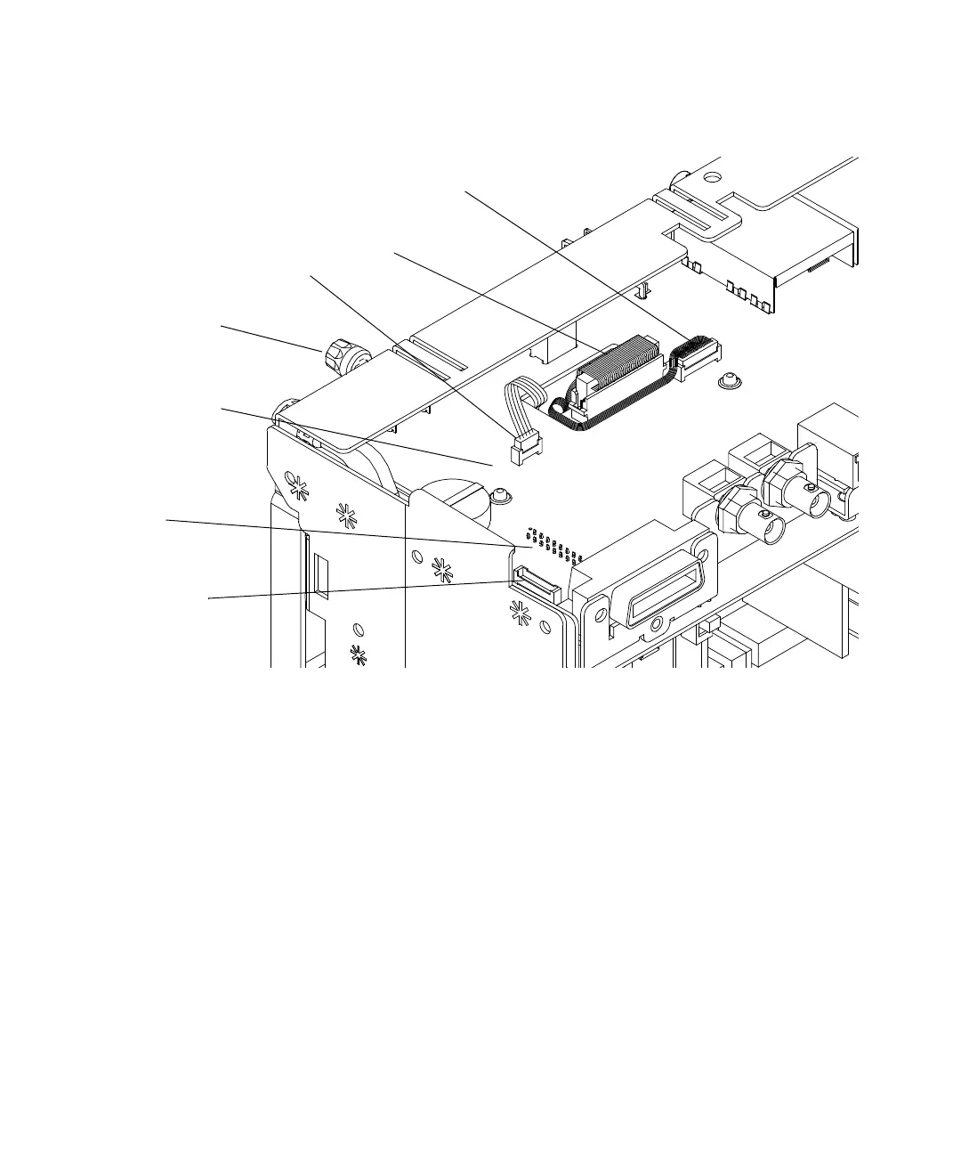
Figure 39 Preparing to remove the system board
3 Disconnect the power control cable. Note: the power supply
cable must be disconnected from the other side; locate the
power supply cable opening on the AC input board to gain
access to the connector.
4 Remove the intensity knob by grasping the knob with one
hand and gently prying using a flat-blade screwdriver with
the other hand.
Using a twisting motion with the screwdriver rather than
prying prevents marking or damaging the front panel.
5 Remove the 3 or 4 T6 screws located by the BNCs on the front
panel (see Figure 18 on page 83).
6 Remove the two hex nuts and washers from the rear BNCs
using the 5/8-inch socket driver.
Display (LCD)
Cable
System Board
Backlight Inverter Cable
Power Supply Cable
(connector on other
side)
Power control
cable
Keyboard
Ribbon Cable
Intensity knob

 Loading...


