Chapter 3 Installing the Software and Connecting Components
Connecting the Laser
Getting Started Guide 3-15
3
Follow the same procedure to plug the connector on the other end of the
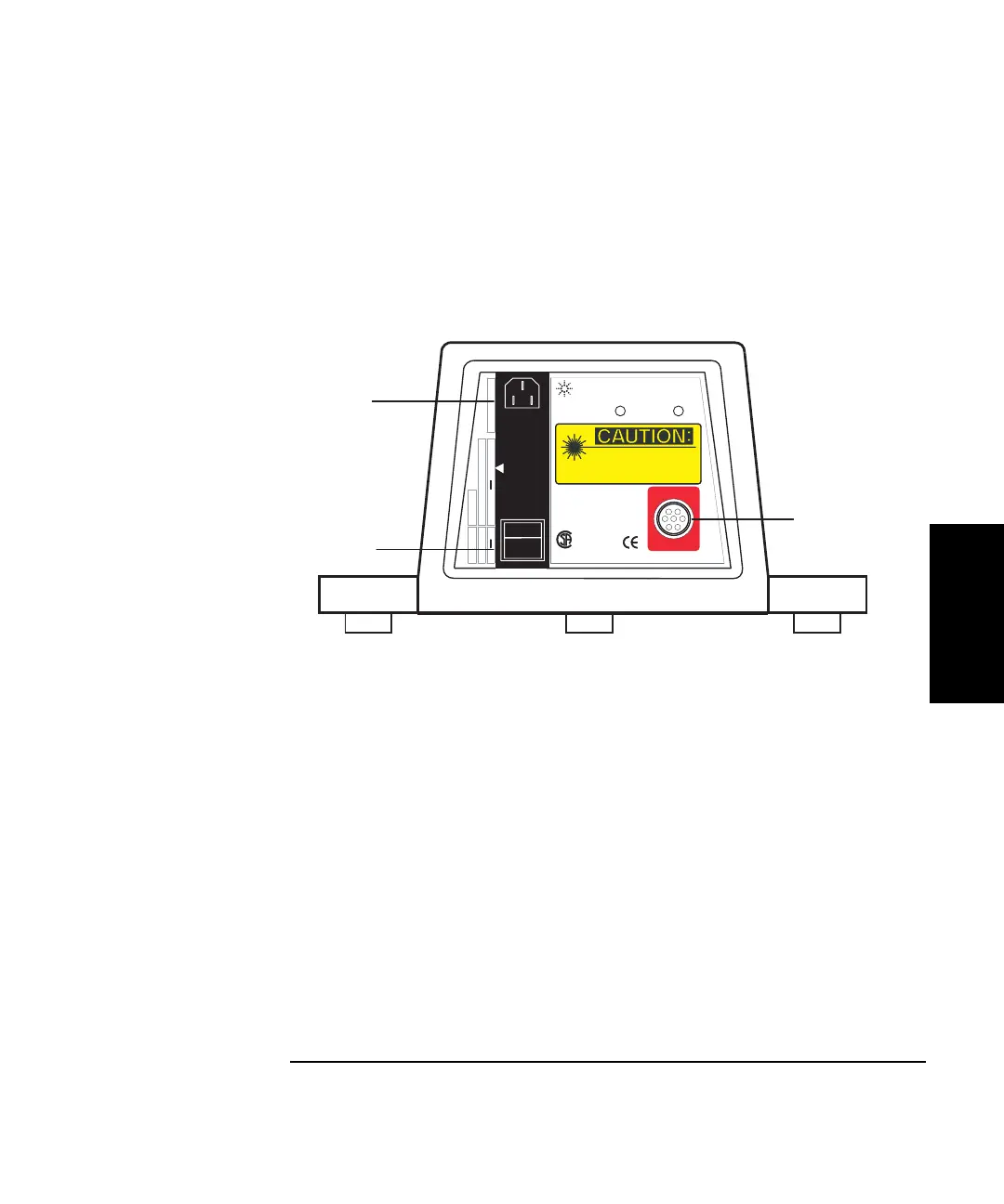
cable into the rear of the laser head (see Figure 3-12). Align the red dot on
the cable connector with the small dot above the laser head connector.
Figure 3-12. Laser head power connector and power switch
If you are not using the optional remote control unit, and if you do not
wish to connect an encoder to the 5530 Dynamic Calibrator, then you are
ready to power up the system. Proceed to the section “Connecting and
Turning on Power” on page 3-18.
To use the USB axis module's A-quad-B encoder input, connect it to the A-
quad-B encoder output of the machine being calibrated, using an
Agilent 10887-60202 A-quad-B cable assembly. Some preparation of the
cable may be necessary. Refer to additional information in “Agilent 10887-
60202 A-quad-B Cable Assembly” on page 3-17.
1
Power connector
2 Power switch
3 Port for Agilent 10882A
cable that connects the
laser head to the PC
3
2
1
AC LINE :Fuse :
100-240VAC 50/60/400 Hz
1.5A 250V
65VA MAX
LASER HEAD
Laser On
Ready
Laser radiation Do not stare into beam.
Maximum Output: 1 mw
Laser Medium: Helium Neon
Pulse Spec: Continuous Wave
Class II
Laser Product
Complies with 21CFR 1040.10 & 1040.11
PAR PERSONNEL QUALIFIE
POUR USAGE EN LABORATOIRE
QUALIFED PERSONAL
FOR LABORATORY USE BY
5519A
Agilent
0
l
USE ONLY
WITH
250V FUSES
 Loading...


