Chapter 4 Using the Agilent 5530 for the First Time
Task 1: Assembling and Connecting Components
4-4 Getting Started Guide
4
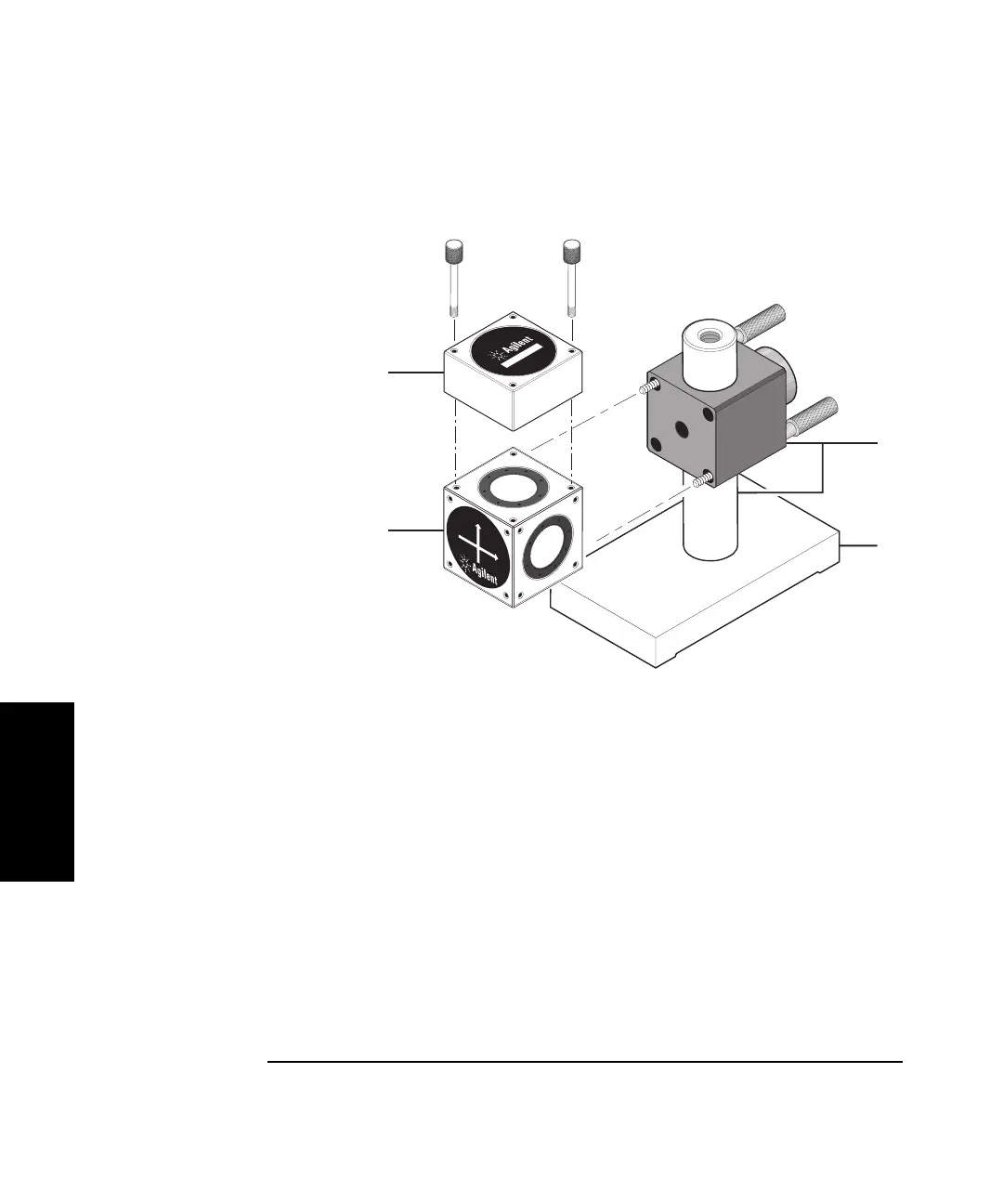
Figure 4-2. Assembling the interferometer
6 Place the interferometer assembly about 1 cm (1/2 inch) away from the
straightedge approximately 5 cm (2 inches) from the front of the laser
head as shown in Figure 4-1.
Note the direction of the arrows on the interferometer label. These arrows
indicate the direction of the laser beam as it exits the interferometer.
Make sure one arrow points to the retroreflector.
7 Assemble the retroreflector as shown in Figure 4-3.
8 Place the retroreflector against the straightedge as shown in Figure 4-1.
1
Linear retroreflector
2 Height adjuster and post
3 Base
4 Linear interferometer
1
4
1
0
7
8
5
A
H
E
I
G
H
T
A
D
J
U
S
T
E
R
A
3
2
1
0
7
6
6
A
L
I
N
E
A
R
I
N
T
E
R
F
E
R
O
M
E
T
E
R
1
0
7
6
7
A
L
I
N
E
A
R
R
E
T
R
O
R
E
F
L
E
C
T
O
R
1A
 Loading...


