158 Operation Manual
10 Configuration
If other columns are currently defined, they may not use
AUX 1, Front inlet, Front detector, or Back detector in their
configuration.
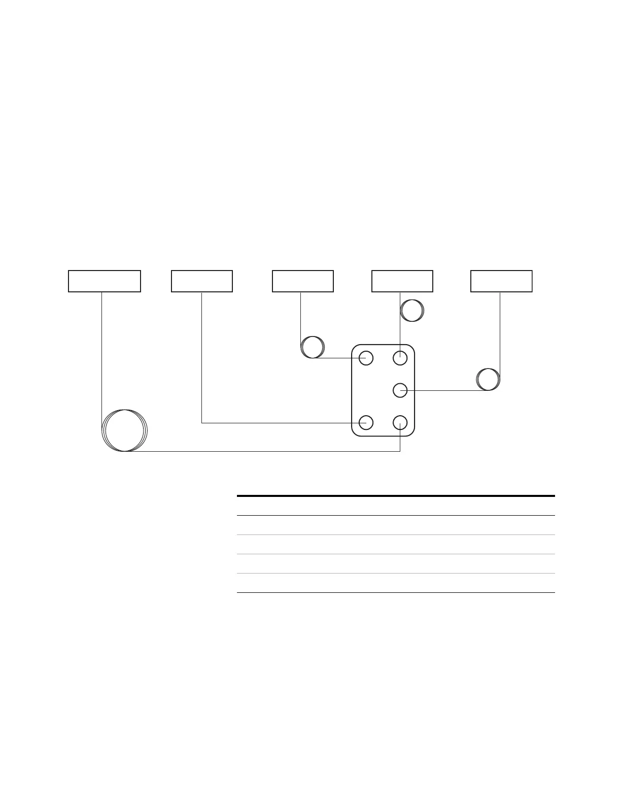
Complicated example
The inlet feeds the analytical column which ends at a
three- way splitter. The splitter has the column effluent and
makeup gas coming in, and transfer lines (non- coated
columns) to three different detectors. This is a case where a
sketch is necessary.
The oven was chosen for the MSD line since most of it is in
the oven.
As in the previous examples, your analytical method can
control the flow of column # 1 which has a GC pressure
controlled inlet and outlet.
Split/splitless inlet
30 m x 0.25 mm x 0.25 µm HP-MS5
0.507 m x 0.10 mm x 0 µm 0.532 m x 0.18 mm x 0 µm
1.444 m x 0.18 mm x 0 µm
µECDAux EPC FPD MSD
Table 21 Splitter with makeup and multiple detectors
Column Inlet Outlet Thermal zone
1 - 30 m × 0.25 mm × 0.25 µm Front inlet Aux EPC 1 GC oven
2 - 1.444 m × 0.18 mm × 0 µm Aux EPC 1 MSD GC oven
3 - 0.507 m × 0.10 mm × 0 µm Aux EPC 1 Front detector GC oven
4 - 0.532 m × 0.18 mm × 0 µm Aux EPC 1 Back detector GC oven

 Loading...


