144 Chapter3
Manual Adjustment Procedures
9 . Demodulator Adjustment
5. Set the oscilloscope controls as follows:
Channel 1 ......................................................................... on
Channel 2 ......................................................................... off
Channel 1 .....................................................50mV/division
Channel 1 ..........................................................................ac
Channel 1 ................................................................. BWlim
Time base .................................................... 1.0ms/division
Trigger .......................................................................... auto
Trigger source .................................................................... 1
Trigger level ................................................................. 0.0V
6. On the spectrum analyzer, press
PRESET, then set the controls as
follows:
Center frequency .................................................. 100MHz
Span .......................................................................... 5MHz
Reference level .......................................................−10dBm
Resolution bandwidth ............................................100kHz
7. On the spectrum analyzer press:
PEAK SEARCH, MARKER →CF SPAN,
ZERO SPAN AUX CTRL, AM/FM DEMOD, FM DEMOD ON OFF(ON) CAL,
IF ADJ ON OFF (OFF) TRIG, and SWEEP CONT SGL (SGL). Set the
volume control to midrange.
8. A 1 kHz sine wave should be observed on the oscilloscope. Rotate the
volume knob on the front panel of the spectrum analyzer until the
amplitude of the 1 kHz signal is at about 150 mV (3 divisions on the
oscilloscope).
9. Adjust A4C707 FM DEMOD for a maximum peak-to-peak response
on the oscilloscope.
10.Press
LINE to turn the spectrum analyzer off. Disconnect the test
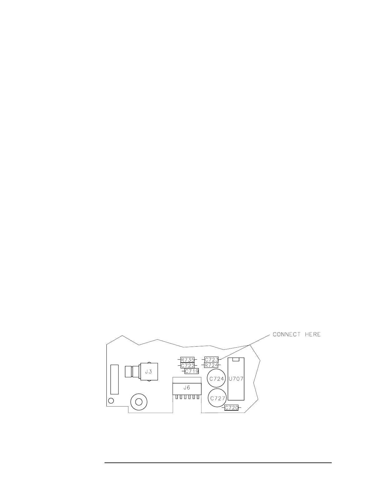
cable from A4C723.
Figure 3-19 Demodulator Adjustment Locations
 Loading...


