478 Chapter9
IF Section
Cal Oscillator (P/O A4 Assembly)
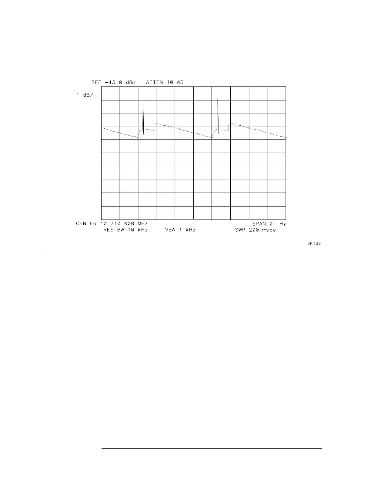
Figure 9-25 Failed Crystal Set Symptoms
Low-Pass Filter
Refer to function block AB of A4 Log Amplifier Schematic Diagram
(sheet 4 of 4) in the 8560 E-Series Spectrum Analyzer Component Level
Information.
1. Connect a DVM positive probe to A4J9 pin 4.
2.On the 8564EC or 8565EC spectrum analyzer, press
CAL.
3. Press
FULL IF ADJUST. Observe the DVM reading between the
displayed messages IF ADJUST STATUS: 300 kHz RBW and
IF ADJUST STATUS: 3 kHz RBW. During this time period, the
voltage should be within a 2 to 10 Vdc range.
4. Observe the DVM reading while IF ADJUST STATUS: AMPLITUDE is
displayed. The reading should be within the 2 to 10 Vdc range.
5. If the DVM reading is outside the range in step 3 but inside the
range in step 4, suspect one of the reactive components in the filter.
 Loading...


