Chapter 9 431
IF Section
Troubleshooting Using the Diagnostic Software
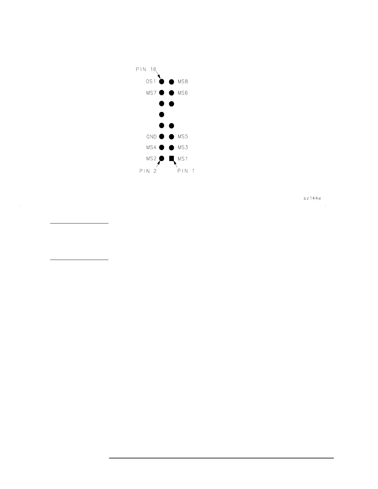
Figure 9-2 A4 and A5 Test Connector Pin Locations
NOTE Because the cal oscillator circuitry on the A4 assembly is such an
integral part of the IF adjustment, always check this assembly first,
before checking the rest of the IF Section. A faulty cal oscillator can
cause many apparent "faults" in the rest of the IF Section.
Troubleshooting the Cal Oscillator on A4 Using
Diagnostic Software
1. From the 8564E/8565E adjustment/diagnostic software menu, select
"CAL Oscillator Control."
2.Set the 8564EC or 8565EC to external trigger and press
SGL SWP, CAL, and IF ADJ OFF.
3. Using a second spectrum analyzer, look at the output of the cal
oscillator at A4J8. Set the second spectrum analyzer to external
trigger (positive-edge) and use the signal at A4U104 pin 2, with
ground connection at A4U104 pin 10, to externally trigger the
second spectrum analyzer. (A 20-pin IC clip is recommended to avoid
inadvertently shorting pins together on A4U104.)
4. Select cw frequencies of 9.9 MHz, 10.7 MHz, and 11.5 MHz in the
diagnostic software menu. The amplitude should be −35 dBm at each
frequency.
5. Select the 20 kHz sweep width in the software menu. The display on
the second spectrum analyzer should be similar to that shown in
Figure 9-3 on page 433.
 Loading...


