84 Chapter2
Adjustment/Diagnostic Software
To Use the Diagnostics
Cal Oscillator Control
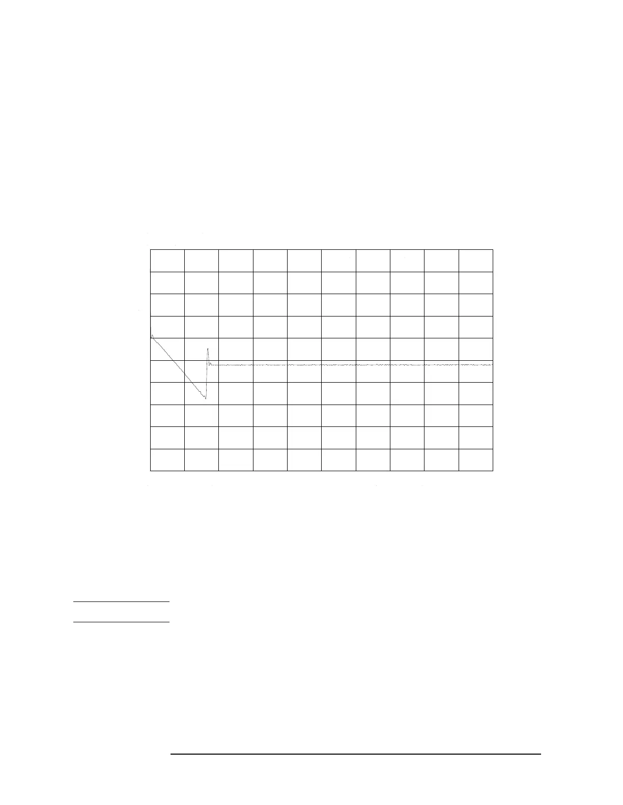
1. Using another spectrum analyzer, look at the output of the cal
oscillator. Refer to the A4 schematic diagram in the
8560 EC-Series
Spectrum Analyzer Component Level Information and 8560 E-Series
Spectrum Analyzer Component Level Information. The display on the test
spectrum analyzer should be similar to that shown in Figure 2-9 on
page 84.
Figure 2-9 CAL Oscillator Swept Output, 20 kHz Width
2. Use the up/down arrows (▲, ▼) on the controller keyboard to select
CF, Sweep Width, or RF On/Off for the cal oscillator.
3. Use the left/right arrows (▲, ▼) to change parameters within each
selection.
NOTE You can select sweep width only when CF is at 10.7 MHz.
 Loading...


