68 Chapter2
Adjustment/Diagnostic Software
4. LOMA Adjustments
4. LOMA Adjustments
Assembly Adjusted
A14 frequency control assembly
Related Performance Test
1ST LO OUTPUT Amplitude
Procedure
CAUTION When connecting the 8587A power sensor to the 1 ST LO OUTPUT, be
sure to use proper adapters. Failure to do so will result in damage to the
expensive connector of the power sensor.
NOTE On the DVM, "Front terminals" must be selected or the adjustment
program will not run.
Carefully follow the instructions issued by the software program.
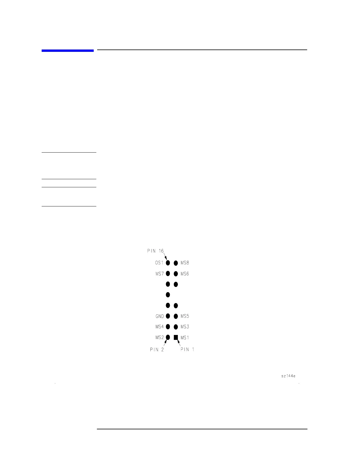
See Figure 2-4 on page 68 for test connector pin locations.
Figure 2-4 A14J18 and A14J15 Pin Locations
 Loading...


