Chapter 2 51
Adjustment/Diagnostic Software
Introduction
Instrument Service Position
Refer to Chapter 4 for information on removing the spectrum analyzer
cover assembly and accessing all internal assemblies.
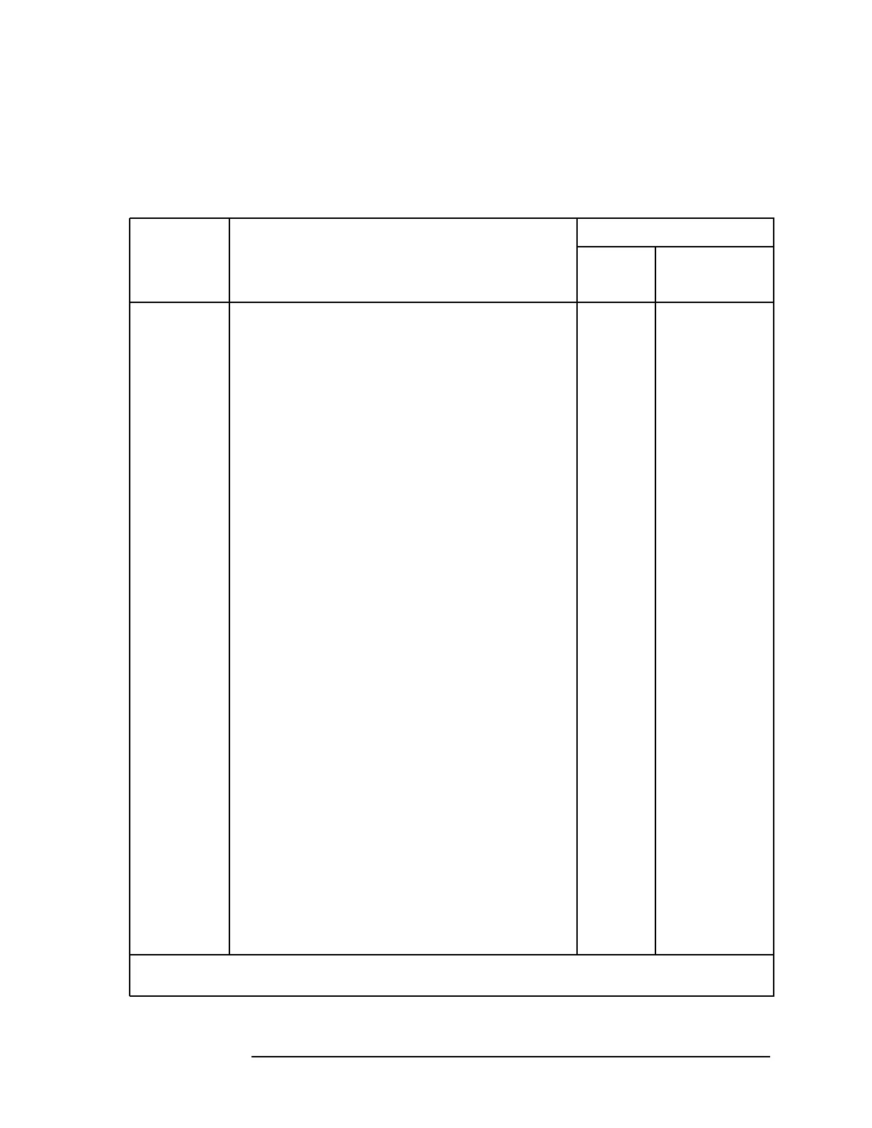
Table 2-1 Related Adjustments
Assembly
Changed
or
Repaired
Perform the following related
adjustments in the order listed
Adjustment Number
Manual Automated*
A1A1
keyboard
No related adjustment
A1A2 RPG No related adjustment
A2
controller
If EEROM from old A2 controller could not be
usedinnewA2orifEEROMmustbereplaced,
also perform the following adjustments:
LOMA adjustments4
External mixer amplitude adjustment or
3rd amp/2nd IF align
†
11 5
Front end cal7
A3 interface Front end cal 7
A4 log
amp/cal osc
Demodulator adjustmen
t9
IF amplitude adjustment
†
29
DC log amplifier adjustment
†
3 10
A5 IF
IF bandpass adjustment
†
1 8
IF amplitude adjustment
†
29
A6 power No related adjustment
supply
*If any automated adjustment is required, you must first perform automated
adjustment “1. Initial Information” on page 63
.
 Loading...


