Chapter 3 171
Manual Adjustment Procedures: 3335A Source not Available
3a. DC Log Amplifier Adjustments
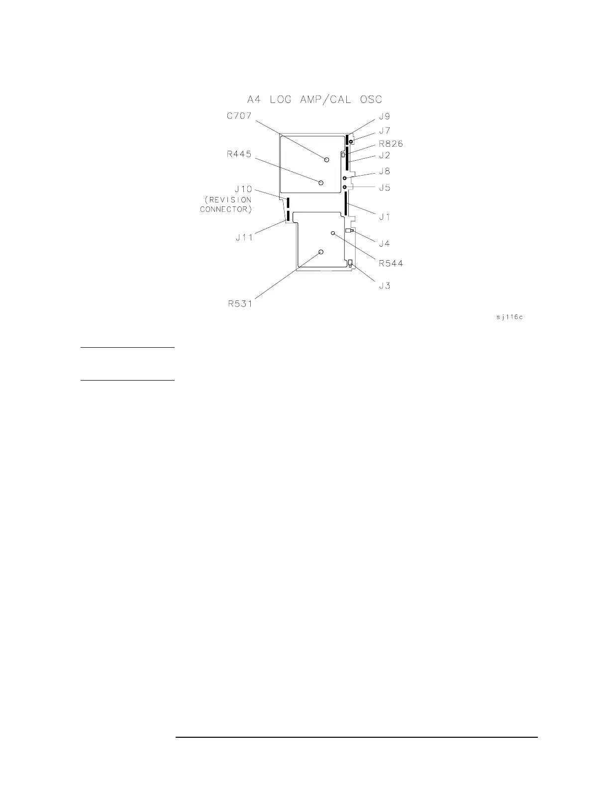
Figure 3a-4 DC Log Adjustment Locations
NOTE Adjustments should be made with all of the shields on and only after
allowing at least a 20 minute warmup.
A4 Limiter Phase Adjustment
1. Press LINE to turn the spectrum analyzer off. Remove the spectrum
analyzer cover and place the spectrum analyzer in the service
position as illustrated in Figure 3a-3. See Figure 3a-4 for adjustment
location.
2. Connect the E4421B RF output to the spectrum analyzer 50Ω input.
Press
LINE to turn the spectrum analyzer on.
3. Set the spectrum analyzer controls as follows:
Center frequency . . . . . . . . . . . . . . . . . . . . . . . . . . . . . . . 15 MHz
Span . . . . . . . . . . . . . . . . . . . . . . . . . . . . . . . . . . . . . . . . . . . . 0 Hz
Reference level . . . . . . . . . . . . . . . . . . . . . . . . . . . . . . . . . . . . −10 dBm
dB/division . . . . . . . . . . . . . . . . . . . . . . . . . . . . . . . . . . . 1 dB/DIV
Resolution bandwidth . . . . . . . . . . . . . . . . . . . . . . . . . . . 300 kHz
IF ADJ . . . . . . . . . . . . . . . . . . . . . . . . . . . . . . . . . . . . . . . . . . OFF
 Loading...


