EasyManuals Logo

Agilent Technologies 8565EC Service Guide

Agilent Technologies 8565EC
512 pages
To Next Page IconTo Next Page
To Previous Page IconTo Previous Page
Page #397 background imageLoading...
Page #397 background image
524 Chapter11
Synthesizer Section
Test Connector Locations
When troubleshooting suspected faulty circuits, use Table 11-1 on
page 525 to determine which procedure to perform.
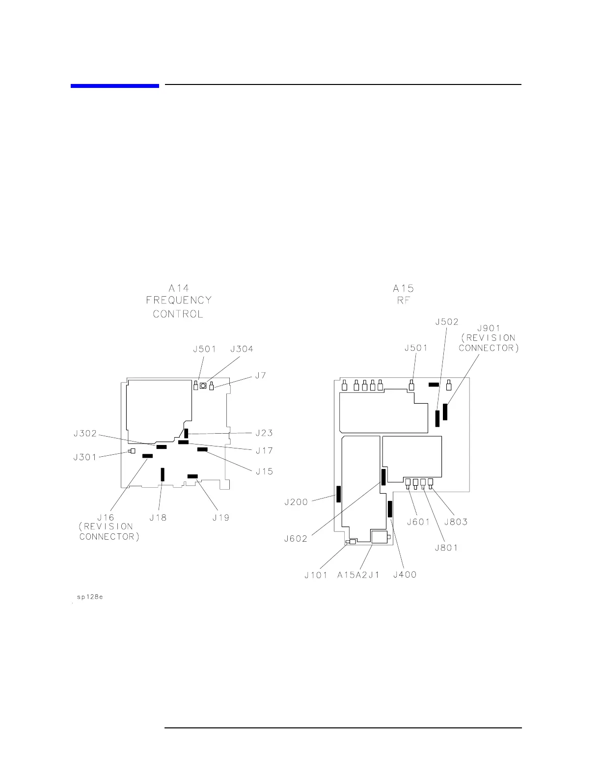
Figure 11-1 illustrates test connector locations on the A14 and A15
assemblies.
The pin locations of a 16-pin test connector are indicated in Figure 11-2
on page 525.
Figure 11-1 A14 and A15 Assembly Test Connectors

Table of Contents

Other manuals for Agilent Technologies 8565EC

Questions and Answers:

Question and Answer IconNeed help?

Do you have a question about the Agilent Technologies 8565EC and is the answer not in the manual?

Agilent Technologies 8565EC Specifications

General IconGeneral
BrandAgilent Technologies
Model8565EC
CategoryMeasuring Instruments
LanguageEnglish

Related product manuals