Chapter 3 165
Manual Adjustment Procedures: 3335A Source not Available
2a. IF Amplitude Adjustments
Equipment
Signal Generator. . . . . . . . . . . . . . . . . . . . . . . . . . . . . . . . . E4421B
Adapters
Type N (m) to BNC (f) . . . . . . . . . . . . . . . . . . . . . . . . . . 1250-1476
Type N (f) to 2.4 mm (f) . . . . . . . . . . . . . . . . . . . . . . . . . . . .11903B
Cables
BNC, 122 cm (48 in) . . . . . . . . . . . . . . . . . . . . . . . . . . . . . . .10503A
Test cable . . . . . . . . . . . . . . . . . . . . . . . . . . . . . . . . . . 85680-60093
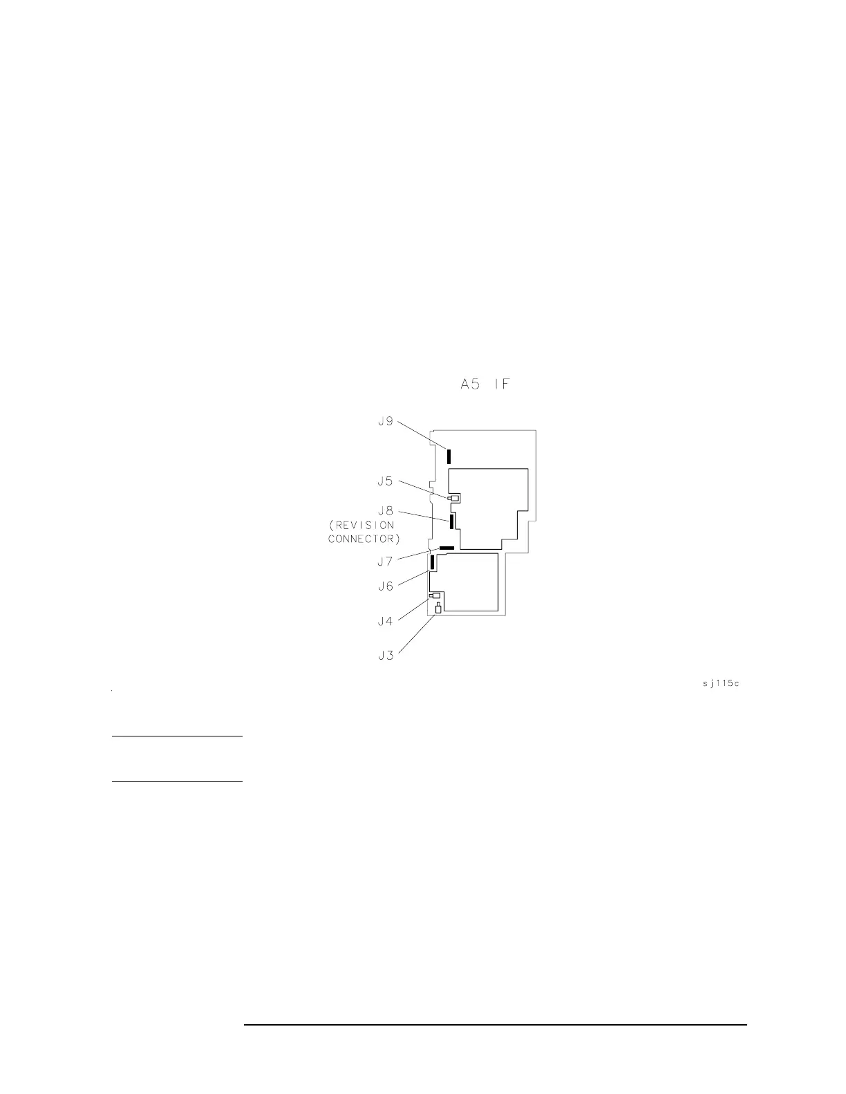
Figure 3a-2 IF Amplitude Adjustment Locations
NOTE The 15 dB reference attenuator adjustment is preset at the factory and
need not be done if the entire A5 IF assembly is replaced.
Procedure
1. Press LINE to turn the spectrum analyzer off. Remove the spectrum
analyzer cover and place the spectrum analyzer in the service
position as illustrated in Figure 3a-1.
2. Disconnect W29, violet coax cable, from A5J3. Connect the test cable
between A5J3 and the RF output of the E4421B. Press
LINE to turn
the spectrum analyzer on.
 Loading...


