532 Chapter11
Synthesizer Section
Confirming a Faulty Synthesizer Section
24.Set the spectrum analyzer and 8340A/B frequencies to the
combinations listed in Table 11-3 on page 533 and press
SGL SWP on
the spectrum analyzer.
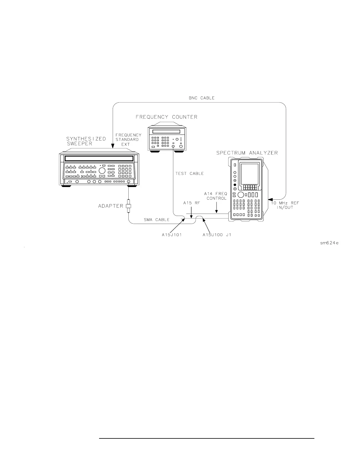
Figure 11-4 Sampler and Sampling Oscillator Test Setup
25.At each combination, the frequency counter should measure a
sampler IF as shown in Table 11-3 on page 533. (The offset PLL
sampling oscillator tunes to the frequencies listed in the table.) If the
frequency counter does not read the indicated sampler IF ±10 kHz,
suspect the A15 RF assembly.
26.Reconnect W34 to A15U100J1 and W32 to A15J101.
27.The 1ST LO OUTPUT, located on the front panel, must be
terminated in 50Ωs. If the YTO unlocks only with certain center
frequency and span combinations, check that the termination is in
place.
28.Set the spectrum analyzer
CENTER FREQ and SPAN to generate the
unlock conditions.
29.On the spectrum analyzer press SGL SWP.
30.Move jumper A14J23 to the TEST position.
31.Disconnect W34 from A15U100J1 and measure the power of the
signal at the end of W34.
 Loading...


