Home
Agilent Technologies
Measuring Instruments
8565EC
Agilent Technologies 8565EC Service Guide
5
of 1
of 1 rating
512 pages
Give review
Manual
Specs
To Next Page
To Next Page
To Previous Page
To Previous Page
Loading...
640
Chapter
13
Display/P
ower Supply Section
T
roub
leshooting the LCD Display
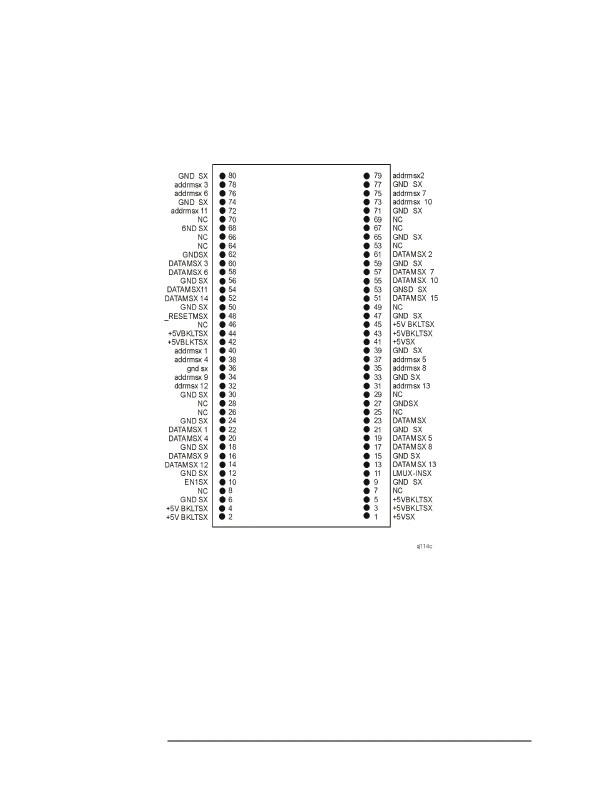
Figure 13-3
Location of +5V supply pins on J1 of A17 and J8 of A2
Figure 13-3 shows A2J8 connections on 8560 EC-Series Instruments
.
Lines 2
−
5 and 42
−
44 supply +5V to the two LCD backlights
. Lines 1
and
41
supply
+5V
to
the
A17A1
Inverter
board.
Lines
1
−
6
and
41
−
44
are identical on A17J1.
497
499
Table of Contents
Table of Contents
5
General Safety Considerations
2
General Information
17
Introduction
18
Conventions Used in this Guide
19
Documentation Outline
19
How to Use this Guide
19
Instrument Variations
20
Serial Numbers and Repair Information
21
Serial Number and Repair Information
21
Service Kit
23
Electrostatic Discharge
24
Reducing Potential for ESD Damage
25
Static-Safe Accessories
25
Returning Instruments for Service
26
Original Packaging
26
Other Packaging
26
Service Tag
26
Returning Instrument for Service
26
Recommended Test Equipment
28
Sales and Service Offices
35
Adjustment/Diagnostic Software
37
Introduction
38
Safety Considerations
39
Which Adjustments Should be Performed
40
Instrument Service Position
41
Getting Started
44
Controller (Computer)
44
Spectrum Analyzers
44
Test Equipment
45
Warm-Up Time
45
Equipment Connections
47
Using the Adjustment/Diagnostic Software
48
To Load the Program
48
To Use the Adjustment Program
49
Automated Adjustments
52
Initial Information
53
LO Frequency
54
Assembly Adjusted
54
Procedure
54
Related Performance Tests
54
YTO FM Coil
56
Assembly Adjusted
56
Procedure
56
Related Performance Tests
56
LOMA Adjustments
58
Assembly Adjusted
58
Procedure
58
Related Performance Test
58
Assembly Adjusted
59
Related Performance Test
59
Procedure
59
Rd Amp/2Nd if Align
59
Assembly Adjusted
60
Related Performance Test
60
Procedure
60
Cal out Adjustment
60
Assembly Adjusted
61
Related Performance Test
61
Procedure
61
Related Performance Tests
61
Procedure
62
IF Bandpass Poles
62
Assembly Adjusted
62
Related Performance Test
62
Procedure
63
IF Amplitude
63
Assembly Adjusted
63
Related Performance Tests
63
Procedure
64
DC Log Adjustment
64
Assembly Adjusted
64
Related Performance Tests
64
Procedure
66
Sampling Oscillator
66
Assembly Adjusted
66
Related Performance Test
66
DAC Control
67
Latch Control
71
Display if CAL Data
71
Cal Oscillator Control
72
IF Diagnostics
73
RF Diagnostics
73
Manual Adjustment Procedures
77
Section 1
78
Introduction
78
Safety Considerations
79
Which Adjustments Should be Performed
79
Test Equipment
79
Adjustable and Factory-Selected Components
80
Adjustment Tools
80
Instrument Service Position
80
Sampling Oscillator
83
Assembly Adjusted
87
IF Bandpass Adjustment
87
IF Amplitude Adjustments
93
DC Log Ampli er Adjustments
98
Sampling Oscillator Adjustment
103
Related Performance Tests
107
YTO Adjustment
107
Equipment
108
Procedure
108
Assembly Adjusted
111
Related Performance Test
111
Calibrator Amplitude Adjustment
111
Description
113
Mhz Reference Adjustment - OCXO
113
Equipment
114
Procedure
115
Mhz Reference Adjustment - TCXO (Option 103)
117
Description
119
Demodulator Adjustment
119
Equipment
120
Assembly Adjusted
122
Description
122
Equipment
122
Related Performance Test
122
External Mixer Bias Adjustment
122
Procedure
123
External Mixer Amplitude Adjustment
124
Assembly Adjusted
124
Description
124
Related Performance Test
124
Equipment
125
Assembly Adjusted
128
Description
128
Equipment
128
Procedure
128
Mhz Reference Adjustment
128
3A. Manual Adjustment Procedures: 3335A Source Not Available
129
Description
132
Equipment
133
Procedure
133
A5 Adjustment Verification
135
A5 Reference Attenuator Adjustment
135
Assembly Adjusted
137
Description
137
Related Performance Tests
137
Equipment
138
A4 Limiter Phase Adjustment
139
A4 Linear Fidelity Adjustment
140
A4 LOG Fidelity Adjustment
141
Assembly Replacement
142
Section 2
143
Introduction
143
Access to Internal Assemblies
144
Cable Color Code
145
Required Tools
145
Procedure 1. Spectrum Analyzer Cover
146
Removal/Replacement
146
Removal of the Front Frame
147
Procedure 2. A1 Front Frame/A18 LCD
147
Removal of the Display Driver Board, Inverter Board, and LCD
149
Removal of the Backlights
150
Removal of the Line Switch from the Front Panel
150
Removal of the Keyboard
152
Replacement of the Front Frame
152
Replacement of the Display Driver Board, Inverter Board, and LCD
154
Replacement of the Keyboard
156
Replacement of the Line Switch
156
Replacing the Backlights
156
Removal
158
Replacement
158
Procedure 3. A1A1 Keyboard/Front Panel Keys
158
Removal
159
Replacement
159
Procedure 4. A1A2 RPG
159
Removal
160
Procedure 5. A2, A3, A4, and A5 Assemblies
160
Removal
167
Procedure 6. A6Powersupplyassembly
167
Replacement
169
Procedure 7. A7 through A13 Assemblies
170
Removal
172
Replacement
172
Removal
173
Replacement
173
A8 Low Band Mixer
173
Removal
174
A9 Input Attenuator
174
Replacement
175
Removal
177
Replacement
177
A10/A12 Rythm/Sbtx
177
A11 Yto
178
Removal
180
A13 Second Converter
180
Replacement
180
Removal
181
Procedure 8. A14 and A15 Assemblies
181
Replacement (Using Contact Removal Tool, Part Number 8710-1791)
182
Procedure 9. B1 Fan
184
Procedure 10. BT1 Battery
185
Procedure 11. Rear Frame/Rear Dress Panel
186
Procedure 15. EEROM
191
Removal/Replacement
191
Procedure 12. EEROM
191
Procedure 16. A21 OCXO
193
Removal
193
Procedure 13. A21 OCXO
193
Replacement
195
Replaceable Parts
196
Introduction
197
Ordering Information
198
Direct Phone-Order System
199
Parts List Format
200
Replaceable Parts
207
Major Assembly and Cable Locations
224
Introduction
225
General Troubleshooting
234
Assembly Level Text
235
Block Diagrams
235
Introduction
235
Assembly Test Points
236
Ribbon Cables
236
Service Cal Data Softkey Menus
241
Troubleshooting to a Functional Section
243
Error Messages
245
Error Message Elimination
246
System Analyzer Programming Errors (100 to 150)
246
Viewing Multiple Messages
246
ADC Errors (200 to 299)
248
LO and RF Hardware/Firmware Failures (300 to 399)
249
Automatic if Errors (400 to 599)
253
Digital and Checksum Errors (700 to 799)
265
System Errors (600 to 651)
265
Battery Problem (718)
267
Model/Option Number Errors (719 to 720)
267
Fast ADC Error (760)
268
Option Module Errors (800 to 899)
268
RAM Check Error (721)
268
System Errors (750 to 759)
268
User-Generated Errors (900 to 999)
269
Block Diagram Description
270
RF Section
272
Synthesizer Section
276
IF Section
278
Adc/Interface Section
279
Controller Section
281
Display/Power Supply Section
282
Adc/Interface Section
287
Section 3
288
Keyboard/Rpg Problems
292
Keyboard Interface
292
RPG Interface
293
Triggering or Video Gating Problems
295
Preselector Peaking Control (Real Time DAC)
298
Flatness Control (RF Gain Dacs)
299
A3 Assembly Video Circuits
301
Log Offset/Log Expand
303
Video MUX
304
Video Filter
305
Video Filter Buffer Amplifier
306
Positive/Negative Peak Detectors
307
Peak Detector Reset
308
Rosenfell Detector
309
Adc Mux
310
Variable Gain Amplifier (VGA)
312
Track and Hold
312
A3 Assembly ADC Circuits
313
ADC Control Signals
313
ADC Start/Stop Control
314
Adc Asm
315
Adc
315
Ramp Counter
316
A3 Assembly Control Circuits
317
Analog Bus Drivers
317
Analog Bus Timing
318
Interface Strobe Select
319
Section 4
323
Troubleshooting Using the Diagnostic Software
325
Troubleshooting the Cal Oscillator on A4 Using Diagnostic Software
326
Troubleshooting A5 Using Diagnostic Software
330
Automatic if Adjustment
332
Parameters Adjusted
333
Requirements
334
Performance Test Failures
336
IF Gain Uncertainty Performance Test
336
Scale Fidelity Performance Test
337
Resolution Bandwidths Performance Tests
337
Performance Test Failures
337
Log Amplifier (P/O A4 Assembly)
338
Log Amplifier
338
Linear Amplifiers
339
Log Amplifier (P/O A4 Assembly)
339
Video Offset
342
Video Output
342
AM/FM Demodulator
343
Frequency Counter Prescaler/Conditioner
343
4.8 Khz if Filters
344
10.7 Mhz if Filters
345
4.8 Khz and 10.7 Mhz if Filters
345
10.6952 Mhz VCXO
346
Input Switch
346
LO Switch
347
Synchronous Detector
347
Log Offset/Gain Compensation
348
Limiter
348
Isolation Amplifier
348
Detector/Mixer
348
Log Offset Compensation
348
Video MUX
349
Log Gain Compensation
349
A5 if Assembly
350
IF Signature
351
A5 if Assembly
351
Common if Signature Problems
357
Mhz Resolution Bandwidth Problems
360
30 Khz Resolution Bandwidth Problems
361
Khz and 10 Khz Resolution Bandwidth Problems
362
Step Gains
363
Cal Oscillator (P/O A4 Assembly)
364
Cal Oscillator Unlock at Beginning of if Adjust
365
Inadequate CAL OSC AMPTD Range
366
300 Hz to 3 Khz Resolution Bandwidth out of Specification
367
Low-Pass Filter
373
AM/FM Demodulation, Audio Amplifier, and Speaker
374
Sweep Generator
374
Section 5
380
Frequency-Count Marker Problems (8564E and 8565E)
382
Frequency-Count Marker Problems (8564EC and 8565EC)
382
Frequency Counter
383
Frequency Counter (8564E and 8565E)
384
Video Input Scaling Amplifiers and Limiter (8564EC and 8565EC)
385
12-Bit Flash ADC (8564EC and 8565EC)
387
Frequency Counter (8564EC and 8565EC)
383
12-Bit Flash ADC
387
Byte Static RAM (8564EC and 8565EC)
388
Reference Clock (8564EC and 8565EC)
389
Reference Clock
389
16 Mhz Harmonic Filter (8564EC and 8565EC)
390
16 Mhz Harmonic Filter
390
State- and Trace-Storage Problems
391
State- and Trace- Storage Problems
391
Keyboard Problems
392
Synthesizer Section
394
Section 6
395
Test Connector Locations
397
Troubleshooting Test Setup
400
Confirming a Faulty Synthesizer Section
401
Confirming a Faulty Synthesizer Section
402
General PLL Troubleshooting
407
PLL Locked at Wrong Frequency
407
Unlocked PLL
408
Operation (100 Mhz VCXO)
410
Troubleshooting (100 Mhz VCXO)
410
Unlocked Reference PLL (100 Mhz VCXO)
410
Third lo Driver Amplifier (100 Mhz VCXO)
414
Unlocked Offset Lock Loop (Sampling Oscillator)
415
Operation
415
Troubleshooting
415
Operation
419
Unlocked YTO PLL
419
Unlocked YTO PLL
420
Troubleshooting an Unlocked YTO PLL
421
Confirming an Unlocked Condition
428
Operation
428
Unlocked Fractional N PLL
428
Fractional N PLL
429
Determining the 1St lo Span
434
Frequency Span Accuracy Problems
434
Confirming Span Problems
435
YTO FM Coil Span Problems (lo Spans 2.01 Mhz to 20 Mhz)
436
YTO Main Coil Span Problems (lo Spans >20 Mhz)
436
YTO FM Coil Span Problems (lo Spans 2.01To 20 Mhz)
436
1St lo Span Problems (All Spans)
438
Fractional N Span Problems (lo Spans ≤2 Mhz)
438
1St lo Span Problems (Multiband Sweeps)
439
Phase Noise in Locked Versus Unlocked Spans
441
Phase Noise Problems
441
Fractional N Versus Offset PLL or YTO PLL Phase Noise
442
Reference Versus Reference PLL Phase Noise
442
Sampler and Sampler if
443
Sweep Generator Circuit
445
A21 Ocxo
450
RF Section
454
Section 7
455
Troubleshooting Using the Diagnostic Software
456
Low Band Problems
460
High Band Problems
461
Low and High Band Problems
462
A7 lo Multiplier and Distribution Amplifier
463
A8 Low Band Mixer
465
A9 Input Attenuator
466
A10 YIG-Tuned Filter/Mixer (RYTHM)
469
A12 Switched Barium-Tuned Mixer (SBTX)
470
A13 Second Converter
471
A14 Frequency Control Assembly
473
LO Multiplier/Amplifier Drive
473
Control Latch for Band-Switch Drivers
476
YTF Driver Circuit
476
A15 RF Assembly
482
Confirming a Faulty Third Converter
482
Confirming Third Converter Output
482
Third Converter
483
Flatness Compensation Control
485
PIN Switch Drivers
485
SIG ID Oscillator (Option 008)
486
10 Mhz Reference
487
Display/Power Supply Section
492
Introduction
493
LCD Display (8564EC and 8565EC)
494
Overview of A17 Display Driver Board
495
Blank Display
496
Troubleshooting the LCD Display
496
DIM Display
497
Troubleshooting Using Part Substitution
497
Troubleshooting Using the VGA Port
497
A6 Power Supply Assembly
499
Power Supply
499
Line Fuse Blowing
500
Low Voltage Supplies
501
Supply Restarting Every 1.5 Seconds (Kick Start)
501
Buck Regulator Control
502
DC-DC Converter Control
503
Power up
503
Component-Level Information Packets
505
Introduction
506
Other manuals for Agilent Technologies 8565EC
User Guide
716 pages
5
Based on 1 rating
Ask a question
Give review
Questions and Answers:
Need help?
Do you have a question about the Agilent Technologies 8565EC and is the answer not in the manual?
Ask a question
Agilent Technologies 8565EC Specifications
General
Brand
Agilent Technologies
Model
8565EC
Category
Measuring Instruments
Language
English
Related product manuals
Agilent Technologies 8560E
716 pages
Agilent Technologies 8561E
716 pages
Agilent Technologies 8563E
716 pages
Agilent Technologies 8564E
716 pages
Agilent Technologies 8564EC
716 pages
Agilent Technologies 8562EC
716 pages
Agilent Technologies 8563EC
716 pages
Agilent Technologies 8504B
296 pages
Agilent Technologies 8594E
673 pages
Agilent Technologies 8593E
673 pages
Agilent Technologies 8591E
673 pages
Agilent Technologies 8590L
673 pages
 Loading...


