118 Chapter3
Manual Adjustment Procedures
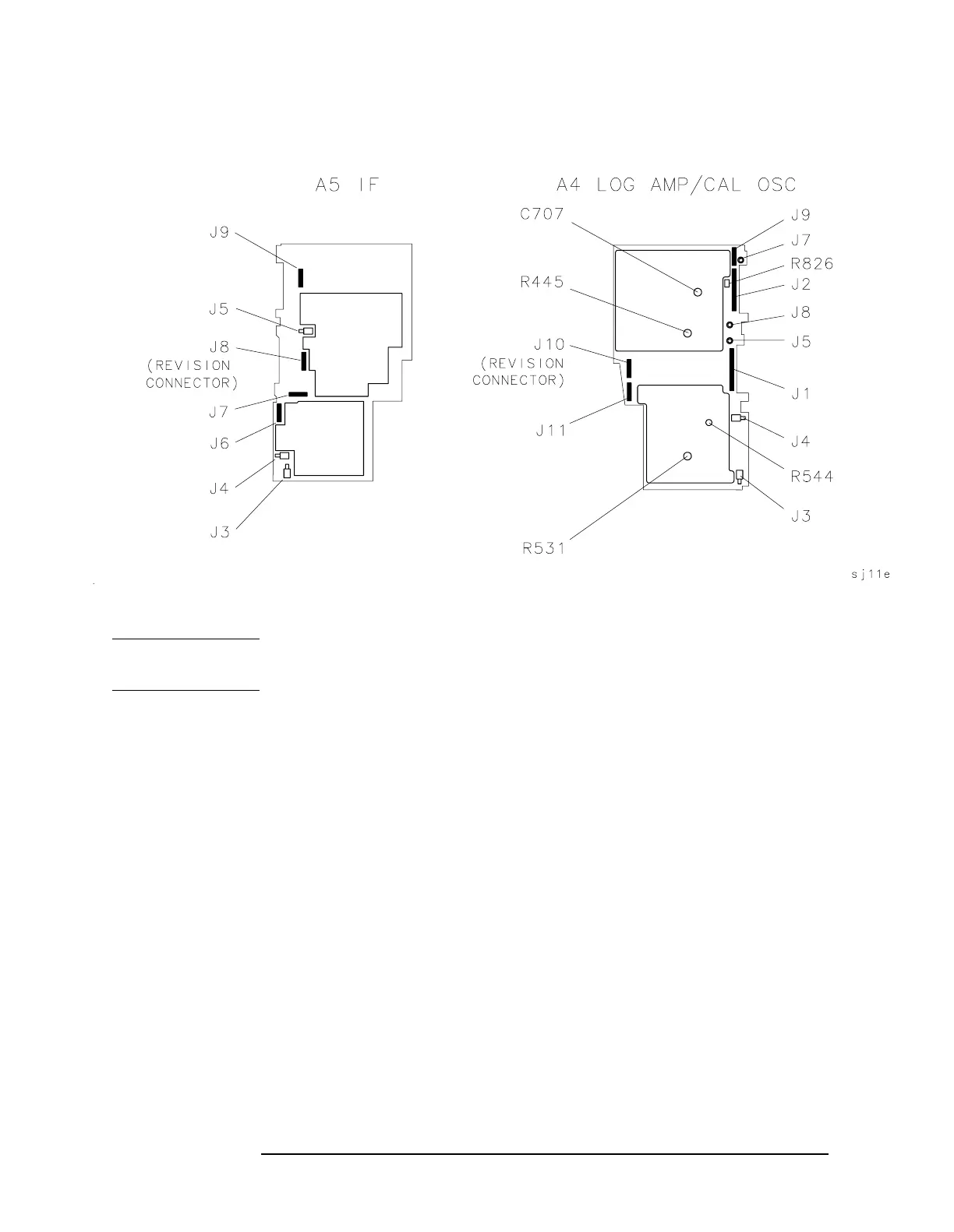
2. IF Amplitude Adjustments
Figure 3-8 IF Amplitude Adjustment Locations
NOTE The 15 dB reference attenuator adjustment is preset at the factory and
need not be done if the entire A5 IF assembly is replaced.
Procedure
1. Press LINE to turn the spectrum analyzer off. Remove the spectrum
analyzer cover and place the spectrum analyzer in the service
position as illustrated in Figure 3-7“IF Amplitude Adjustment
Setup,” on page 117.
2. Disconnect W29, violet coax cable, from A5J3. Connect the test cable
between A5J3 and the 50Ω output of the 3335A. Press
LINE to turn
the spectrum analyzer on.
3. On the spectrum analyzer, press MKR, CAL, and IF ADJ ON OFF so
OFF is underlined.
4. Set the 3335A controls as follows:
Frequency ............................................................... 10.7MHz
Amplitude ................................................................ −55dBm
5. Note the marker value. Ideally it should read −60 dBm ±0.1 dB.
 Loading...


