Service Guide 10-9
8719ET/20ET/22ET Service Key Menus and Error Messages
8719ES/20ES/22ES Service Menus - Internal Diagnostics
RF Network Analyzers
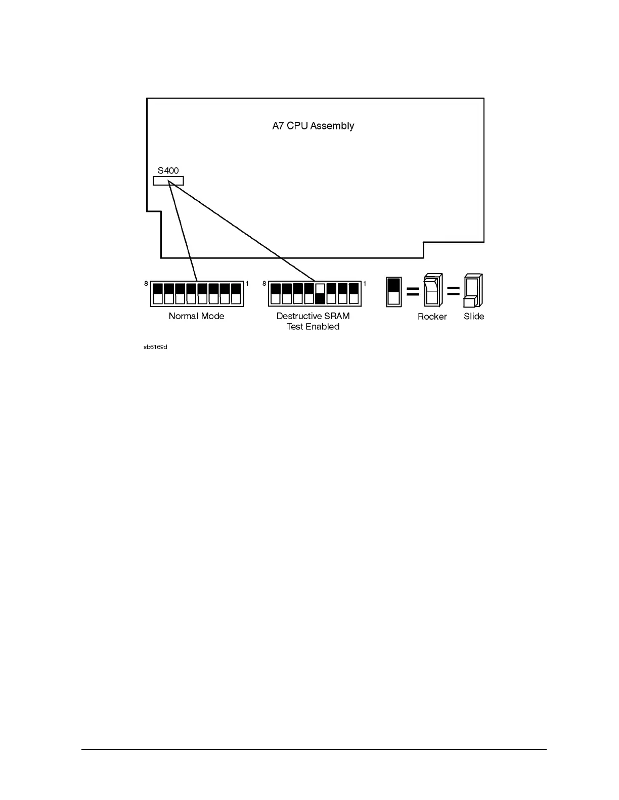
Figure 10-2 Switch Positions on the A7 CPU Board
4 Main DRAM − Verifies the A7 CPU main memory (DRAM) with a
non-destructive write/read test pattern. A destructive version of this test is
run during power-on.
For additional information, see “Internal Tests” on page 10-8 and
Chapter 6 , “Digital Control Troubleshooting.”
5 DSP Wr/Rd − Verifies the ability of the main processor and the DSP
(digital signal processor), both on the A7 CPU assembly, to communicate
with each other through DRAM. This also verifies that programs can be
loaded to the DSP, and that most of the main RAM access circuits operate
correctly.
6 DSP RAM − Verifies the A7 CPU RAM associated with the digital signal
processor by using a write/read pattern.
7 DSP ALU − Verifies the A7 CPU high-speed math processing portions of
the digital signal processor.
8 DSP Intrpt − Tests the ability of the A7 CPU digital signal processor to
respond to interrupts from the A10 digital IF ADC.
9 DIF Control − Tests the ability of the A7 CPU main processor to
write/read to the control latches on the A10 digital IF.
10 DIF Counter − Tests the ability of the A7 CPU main processor to
write/read to the triple divider on the A10 CPU. It tests the A7 CPU data
buffers and A10 digital IF, the 4 MHz clock from the A12 reference.
 Loading...


