2-28 Service Guide
System Verification and Performance Tests 8719ET/20ET/22ET
System Verification 8719ES/20ES/22ES
RF Network Analyzers
CAUTION Be very careful not to drop the airline’s center or outer conductor. Irreparable
damage will result if these devices are dropped.
During this procedure, you will be touching the exposed center conductor of
the test port with the center conductor of the airline. Ground yourself to
prevent electrostatic discharge (ESD).
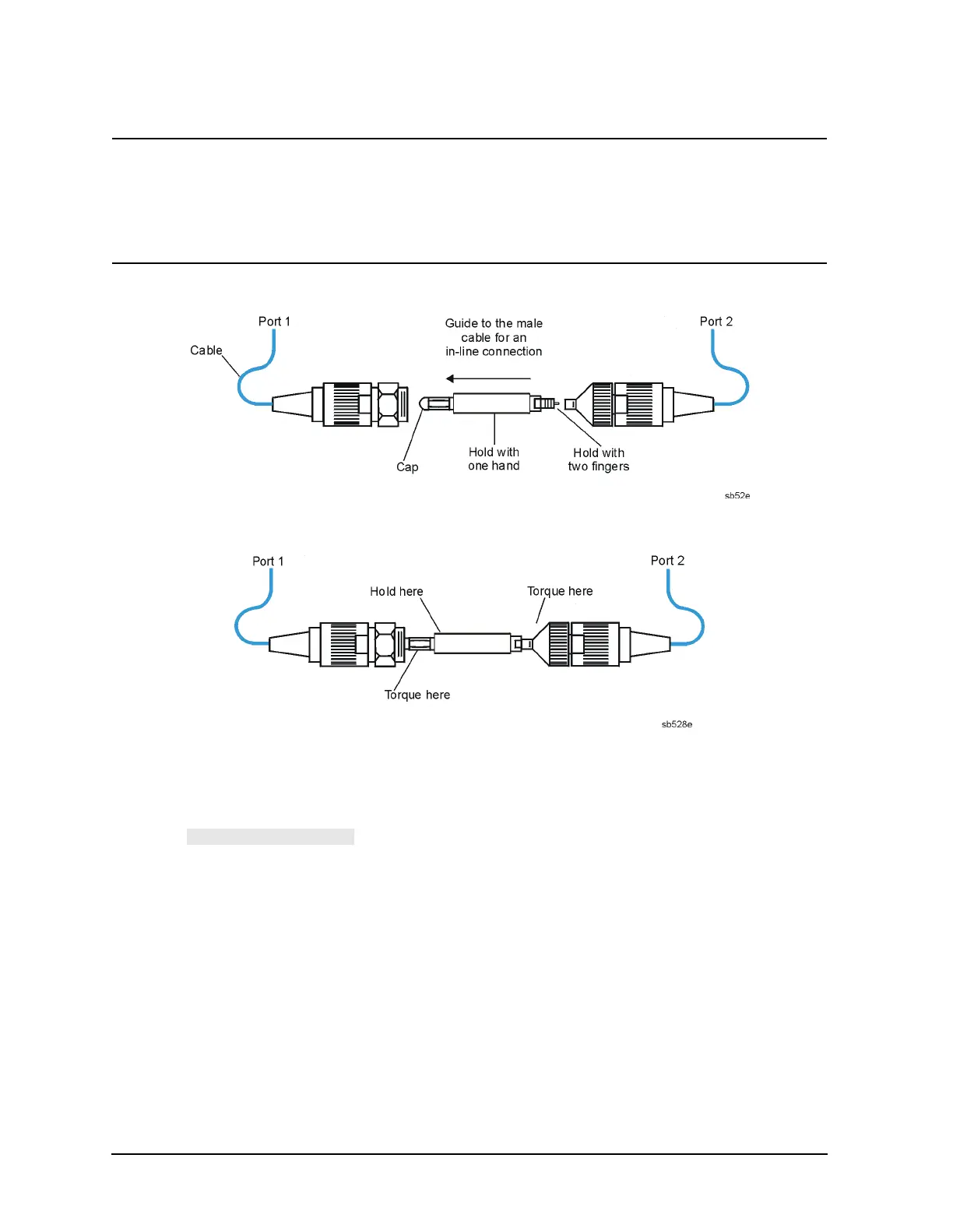
Figure 2-12 Aligning the Center Conductor
Figure 2-13 Torquing the Connection
7. Enter Test 30 (using step keys, entry keys, or front panel knob). Repeat steps 1 through
4 of this section with the 25Ω mismatch airline (Ver Dev 4). Refer to Figure 2-12 and
Figure 2-13.
8. When is active, the printout of the measurements shows both a
plot of the measurement and a list of the measured frequencies with corresponding
data. The plot includes the measured data trace, factory supplied data trace and
uncertainty limits. The listing includes measured data and uncertainty limits. If there
is a failure at any frequency, an asterisk will be displayed next to the measured data
and the out-of-specification measured data on the plot will be blanked out.
 Loading...


