Service Guide 2-37
8719ET/20ET/22ET System Verification and Performance Tests
8719ES/20ES/22ES Performance Tests
RF Network Analyzers
4. On the analyzer, press the following:
5. Enter the power value listed in Table 2-8 and then press .
6. To set a 300 second sweep, press .
7. To initiate a single sweep, press .
8. During the sweep, notice the minimum and maximum power level readings, and record
these in the “Min.” and “Max.” columns on the “Level Accuracy” performance test
record.
The analyzer remains at each frequency point for 1.5 seconds to allow the power meter
sufficient time to settle.
If the Analyzer Fails This Test
1. Ensure that the power meter and power sensor are operating to specification.
2. Inspect the connectors for damage. Poor match at these connections can generate power
reflections and cause the analyzer to appear to be out of limits.
3. Marginal failures (especially at the high or low end) may be due to the power sensor
calibration factor approximation method. A calibration factor approximation of ±4%, as
in the above example, induces an error of about 0.15 dB. To eliminate the calibration
factor approximation as the cause of failure, do the following:
a. Press and rotate the knob to the frequency in question.
b. Set the calibration factor on the power meter to the value indicated by the power
sensor.
c. The corrected power level reading should be between the limits shown in the “Level
Accuracy” performance test record.
4. The source relies on the power adjustments for proper performance, refer to Chapter 3 ,
“Adjustments and Correction Constants.” If failures still occur, after you have made the
power adjustments, refer to Chapter 7 , “Source Troubleshooting.”
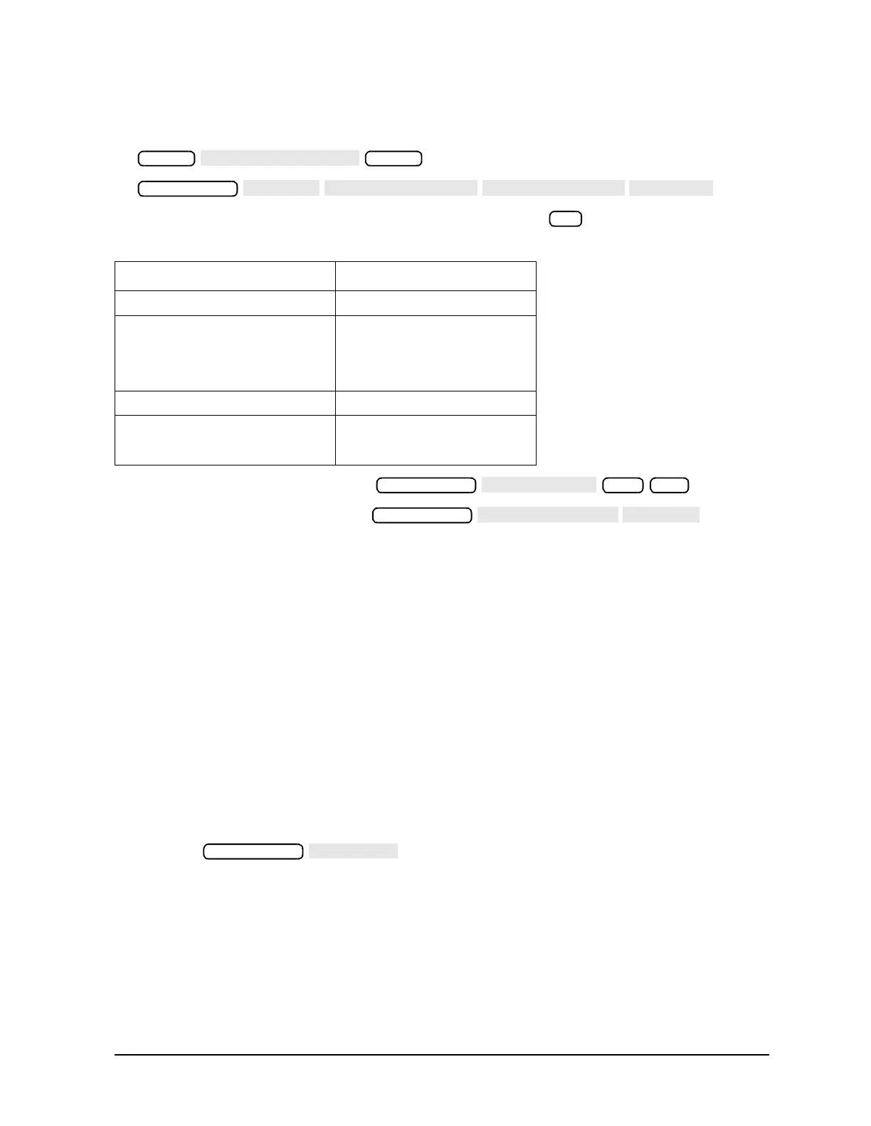
Table 2-8 Power Values for Flatness Test
Analyzer Model Type Test Power Setting
8719ES and 8720ES 0 dBm
8719ET and 8720ET
8719ES Option 007
8720ES Option 007
5 dBm
8722ES −10 dBm
8722ET
8722ES Option 007 −5 dBm
Preset
Preset
x1
Sweep Setup
300 x1
Sweep Setup
 Loading...


