EasyManuals Logo

Allied Telesis IE340 Series Installation Guide

Allied Telesis IE340 Series
136 pages
To Next Page IconTo Next Page
To Previous Page IconTo Previous Page
Page #97 background imageLoading...
Page #97 background image
Chapter 5: Powering On the Switch
97
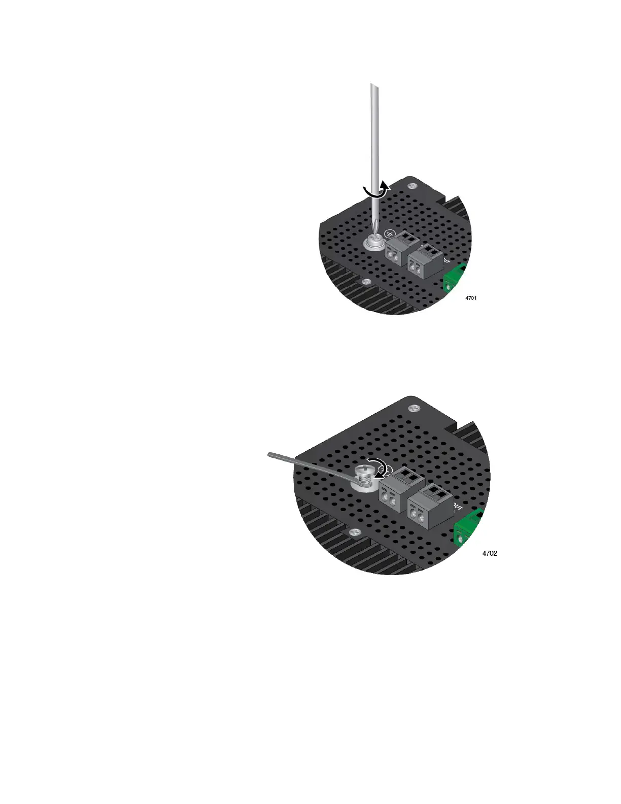
Figure 35. Loosening the Grounding Screw
3. Wrap the grounding wire clockwise around the base of the grounding
screw. Refer to Figure 36.
Figure 36. Wrapping the Grounding Wire Around the Grounding Screw
4. Tighten the screw to secure the grounding wire to the switch. Refer to
Figure 37 on page 98.

Table of Contents

Other manuals for Allied Telesis IE340 Series

Questions and Answers:

Question and Answer IconNeed help?

Do you have a question about the Allied Telesis IE340 Series and is the answer not in the manual?

Allied Telesis IE340 Series Specifications

General IconGeneral
BrandAllied Telesis
ModelIE340 Series
CategorySwitch
LanguageEnglish

Related product manuals