IE340 Series Installation Guide
102
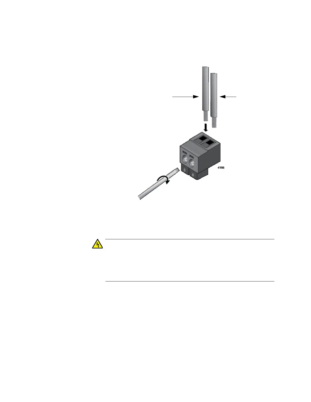
5. Insert the wires into the connector and tighten the retaining screws to
secure the wires. Refer to Figure 43.
Allied Telesis recommends tightening the screws to 2 to 3 in.-lbs.
Figure 43. Inserting the Wires into the DC Cable Connector
6. After attaching the wires to the connector, verify that there are no
exposed wires or loose wire strands. Refer to Figure 50 on page 107.
Check to see if there are any exposed copper strands coming from
the installed wires. When this installation is done correctly there
should be no exposed copper wire strands extending from the
terminal block. Any exposed wiring can conduct harmful levels of
electricity to persons touching the wires. E12
7. Insert the alarm connector back into its connector on the switch. Refer
to Figure 44 on page 103.

 Loading...


