Chapter 3: Installing the Switch
77
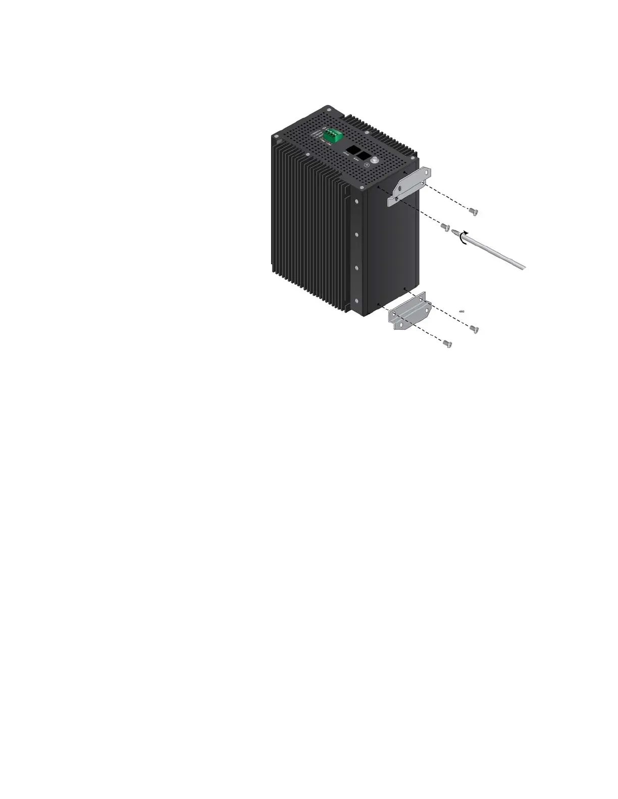
3. Install the two wall brackets to the back panel of the switch, with the
four screws included with the unit. Refer to Figure 25.
Figure 25. Installing the Wall Brackets on the Switch
4. Have another person hold the switch on the plywood base on the wall
while you secure it with four screws (not provided). Refer to Figure 26
on page 78.
Please follow these guidelines as you position the switch on the wall:
The switch must be oriented as shown in Figure 26. Do not install
the switch horizontally or upside-down.
Be sure to leave sufficient space from other devices or walls to
allow for adequate air circulation around and through the cooling
fins. Refer to “Reviewing Site Requirements” on page 59 for further
information.

 Loading...


