IE340 Series Installation Guide
134
RJ-45 Style Serial Console Port Pinouts
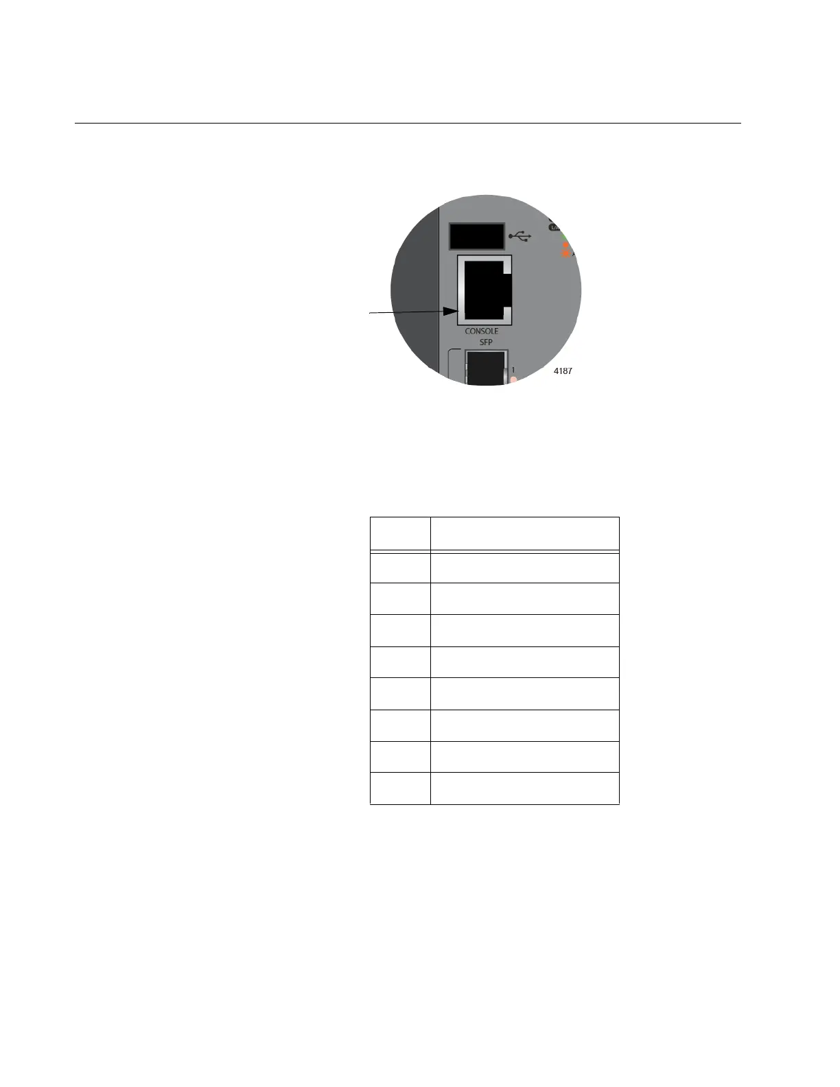
Figure 56 identifies pin 1 on the RJ-45 connector on the Console port.
Figure 56. Console Port Pin Layout (Front View)
Table 25 lists the pin signals for the RJ-45 style serial Console port.
Table 25. RJ-45 Style Console Port Pin Signals
Pin Signal
1Open
2 Looped to pin 7
3 Transmit Data
4 Ground
5 Ground
6 Receive Data
7 Looped to pin 2
8Open

 Loading...


