EasyManuals Logo

Allied Telesis IE340 Series Installation Guide

Allied Telesis IE340 Series
136 pages
To Next Page IconTo Next Page
To Previous Page IconTo Previous Page
Page #103 background imageLoading...
Page #103 background image
Chapter 5: Powering On the Switch
103
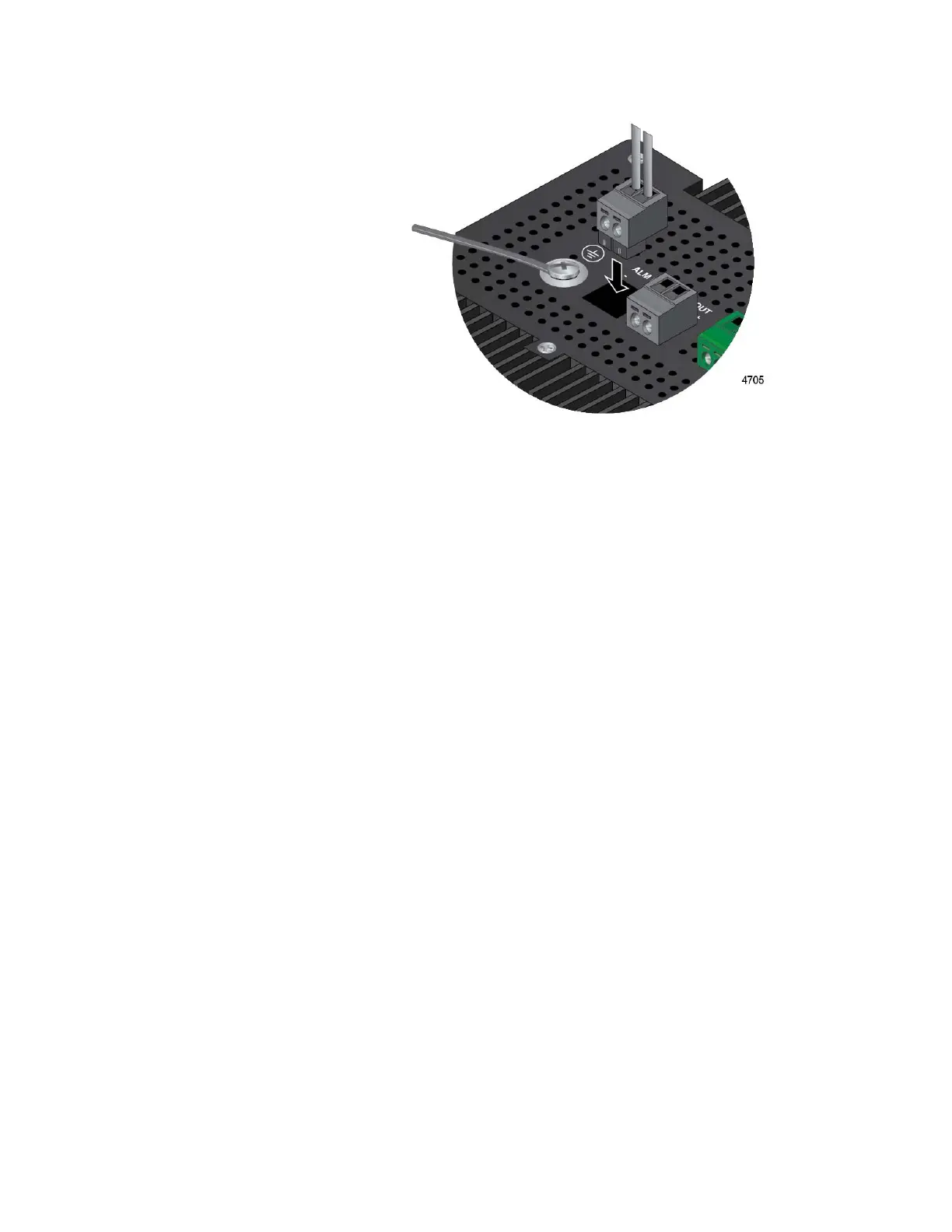
Figure 44. Inserting the DC Connector into the Alarm Connector
8. Connect the other end of the wires to an external sensor for the Alarm
In connector or an alert device for the Alarm Out connector.
9. If necessary, repeat this procedure to wire the other alarm connector.
10. Go to “Preparing the DC Power Cables” on page 104.

Table of Contents

Other manuals for Allied Telesis IE340 Series

Questions and Answers:

Question and Answer IconNeed help?

Do you have a question about the Allied Telesis IE340 Series and is the answer not in the manual?

Allied Telesis IE340 Series Specifications

General IconGeneral
BrandAllied Telesis
ModelIE340 Series
CategorySwitch
LanguageEnglish

Related product manuals