EasyManuals Logo

Allied Telesis IE340 Series Installation Guide

Allied Telesis IE340 Series
136 pages
To Next Page IconTo Next Page
To Previous Page IconTo Previous Page
Page #106 background imageLoading...
Page #106 background image
IE340 Series Installation Guide
106
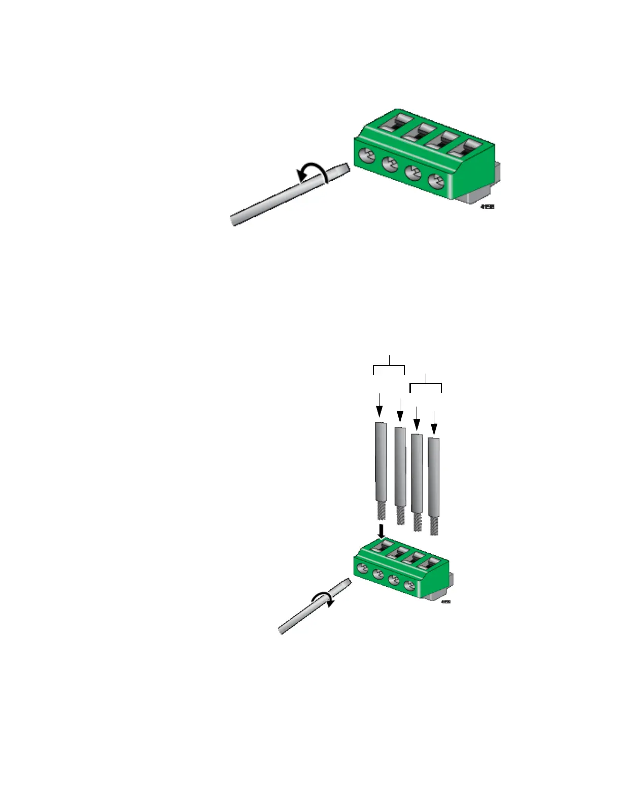
4. Loosen the wire retaining screws in the connector with a #1
screwdriver. Refer to Figure 48.
Figure 48. Loosening the Wire Retaining Screws on the PWR 1 - PWR 2
Cable Connector
5. Insert the wires into the connector and tighten the retaining screws to
secure the wires. Refer to Figure 49.
Allied Telesis recommends tightening the screws to 2 to 3 in.-lbs.
Figure 49. Inserting the Wires into the PWR 1 - PWR 2 Cable Connector
6. After attaching the wires to the connector, verify that there are no
exposed wires or loose wire strands. Refer to Figure 50 on page 107.
+
-
+
-
PWR 1
PWR 2

Table of Contents

Other manuals for Allied Telesis IE340 Series

Questions and Answers:

Question and Answer IconNeed help?

Do you have a question about the Allied Telesis IE340 Series and is the answer not in the manual?

Allied Telesis IE340 Series Specifications

General IconGeneral
BrandAllied Telesis
ModelIE340 Series
CategorySwitch
LanguageEnglish

Related product manuals