IE340 Series Installation Guide
20
Hardware Components
The IE340 switches are Industrial Managed Layer 3 switches that are
designed for high performance in harsh environments. They feature eight
or sixteen twisted pair ports, two or four SFP transceiver slots, and a
Console port for local management. All models, except the IE340-12GT
switch, support PoE+ on the twisted pair ports and all models, except the
IE340L-18GP switch, come with a USB port.
The IE340 switches are listed here:
“IE340-12GP” , next
“IE340-12GT” on page 21
“IE340-20GP” on page 21
“IE340L-18GP” on page 22
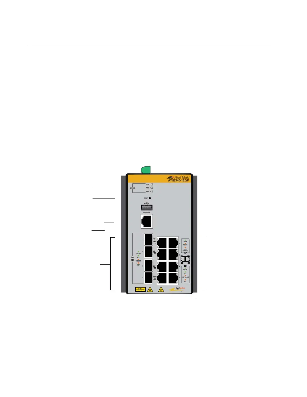
IE340-12GP The front panel of the IE340-12GP switch is shown in Figure 1.
Figure 1. Front Panel of the IE340-12GP Switch
10/100/1000Base-T
twisted pair ports
Slots for
100/1000Base-X
SFP transceivers
Console
management
port
USB port
Status LEDs
Reset button

 Loading...


