IE340 Series Installation Guide
42
IE340L-18GP:
awplus(config)# alarm facility link-down
port1.0.1-port1.0.18 relay
IE340-12GP and IE340-12GT:
awplus(config)# alarm facility link-down
port1.0.1-port1.0.12 relay
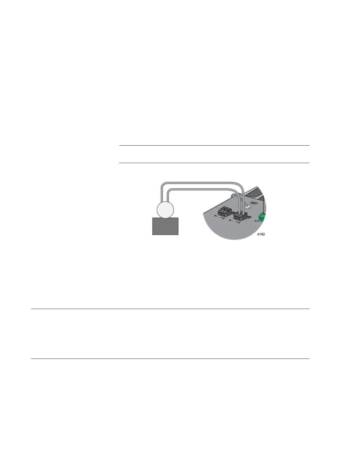
If the switch detects that a port does not have a link, it changes the circuit
from closed to open. The alert device, detecting the change to the circuit,
turns on the LED. When the switch detects that all its ports have links
again, it closes the circuit, which turns off the LED.
Alarm devices are not available from Allied Telesis.
Figure 10. Example of the Alarm Out Port
DIN Rail Bracket
The switch comes with one DIN rail bracket pre-installed on the back
panel. The bracket is compatible with DIN 35 x 7.5mm rails.
Screw Holes for Wall Brackets
The back panel has four holes for securing the two wall brackets included
in the accessory kit.
Blue LED
Circuit closed - LED off
Circuit open - LED on

 Loading...


