EasyManuals Logo

Allied Telesis IE340 Series Installation Guide

Allied Telesis IE340 Series
136 pages
To Next Page IconTo Next Page
To Previous Page IconTo Previous Page
Page #101 background imageLoading...
Page #101 background image
Chapter 5: Powering On the Switch
101
Figure 40. Wrapping the Wire Strands
Note
Allied Telesis recommends tinning the wires with solder for added
protection against loose strands. This guide does not provide
instructions on how to tin wires.
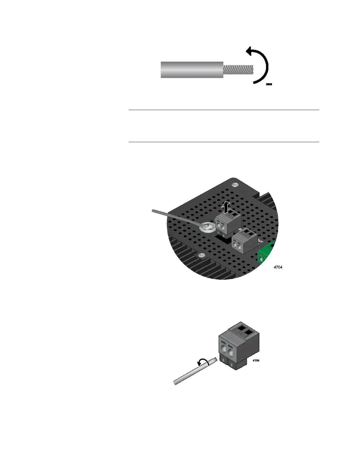
3. Remove the alarm connector from the top panel. Figure 41 shows the
removal of the ALM OUT connector.
Figure 41. Removing an Alarm Connector
4. Loosen the wire retaining screws in the connector with a #1
screwdriver. Refer to Figure 42.
Figure 42. Loosening the Wire Retaining Screws on an Alarm Connector

Table of Contents

Other manuals for Allied Telesis IE340 Series

Questions and Answers:

Question and Answer IconNeed help?

Do you have a question about the Allied Telesis IE340 Series and is the answer not in the manual?

Allied Telesis IE340 Series Specifications

General IconGeneral
BrandAllied Telesis
ModelIE340 Series
CategorySwitch
LanguageEnglish

Related product manuals