Chapter 1: Overview
39
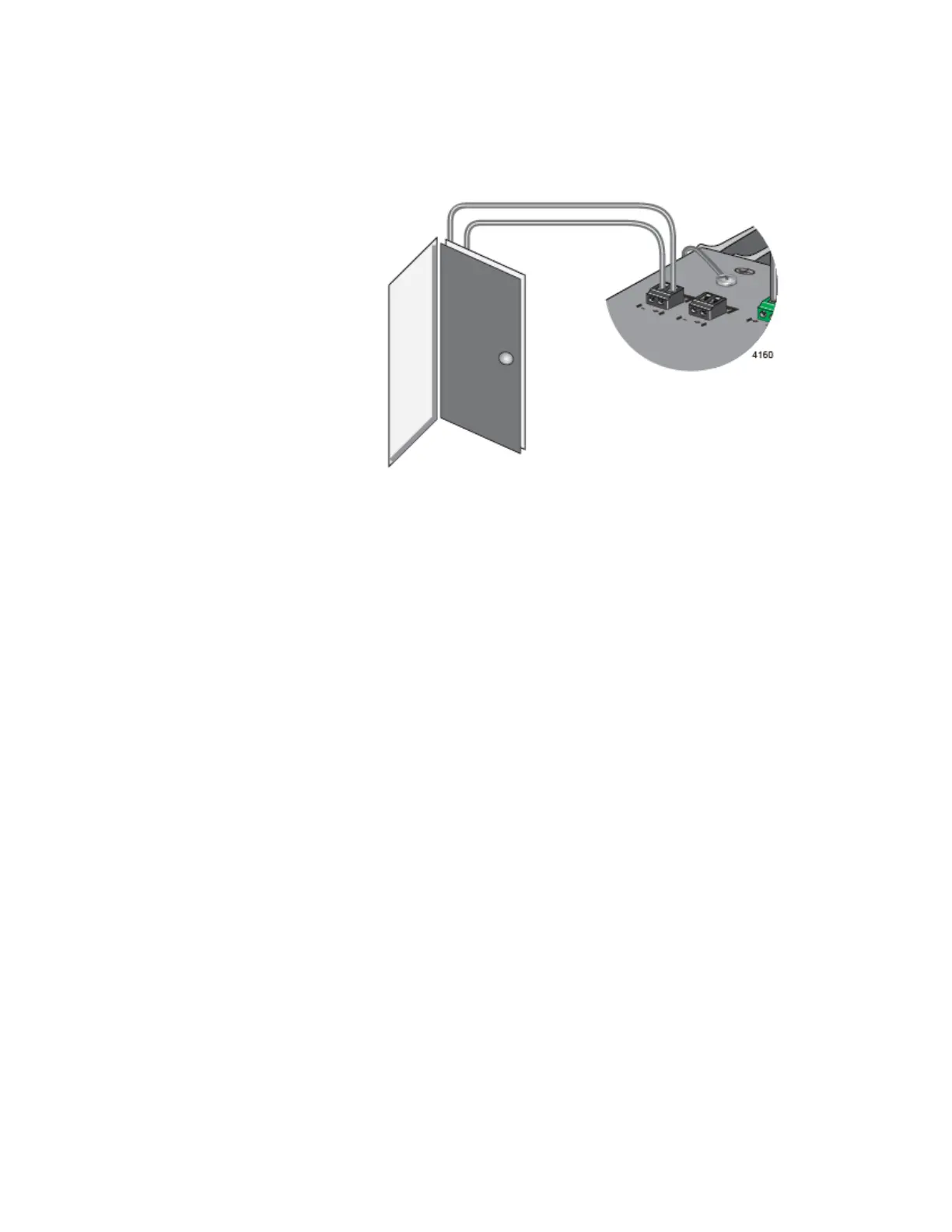
The example in Figure 8 shows the Alarm In connector attached to a door
sensor. The sensor is installed such that it is closed (on) when the door is
closed and open (off) when the door is open.
Figure 8. Example 1 of the Alarm In (ALM IN) Connector
To have the switch generate an alarm when someone opens the door, you
enter the following ALARM FACILITY INPUT-ALARM command. The
command configures the switch to generate an alarm when the state of the
sensor changes from closed to open.
awplus(config)# alarm facility input-alarm 1 alarm-
position open
The alarm remains active until the door is closed again.
In the example in Figure 9 on page 40, the Alarm In connector is
connected to a temperature sensor. The sensor is configured to be open
(off) at temperatures of 30° C or below and closed (on) at temperatures
above 30° C.
Door Sensor:
Door closed - circuit closed
Door open - circuit open
Alarm In connector:
Alarm triggered when circuit
changes to open.

 Loading...


