IE340 Series Installation Guide
108
Powering On the Switch
This section contains the procedure for powering on the switch.
The switch can update its release or configuration file from a USB
flash drive during the initial power up of the unit. This is called the
Autoboot feature. Using the Autoboot feature is optional. It is only
available during the initial power up of the unit. To use the feature,
insert a USB flash drive with the appropriate files into the USB port
on the switch before powering on the unit. For more information on
the feature, refer to the Software Reference for the IE340 Switches.
For power supply requirements, refer to “Power Supplies” on page 49. To
power on the chassis, perform the following procedure:
1. Verify that the DC power supply is powered off. If there are two DC
power supplies, verify that both units are powered off.
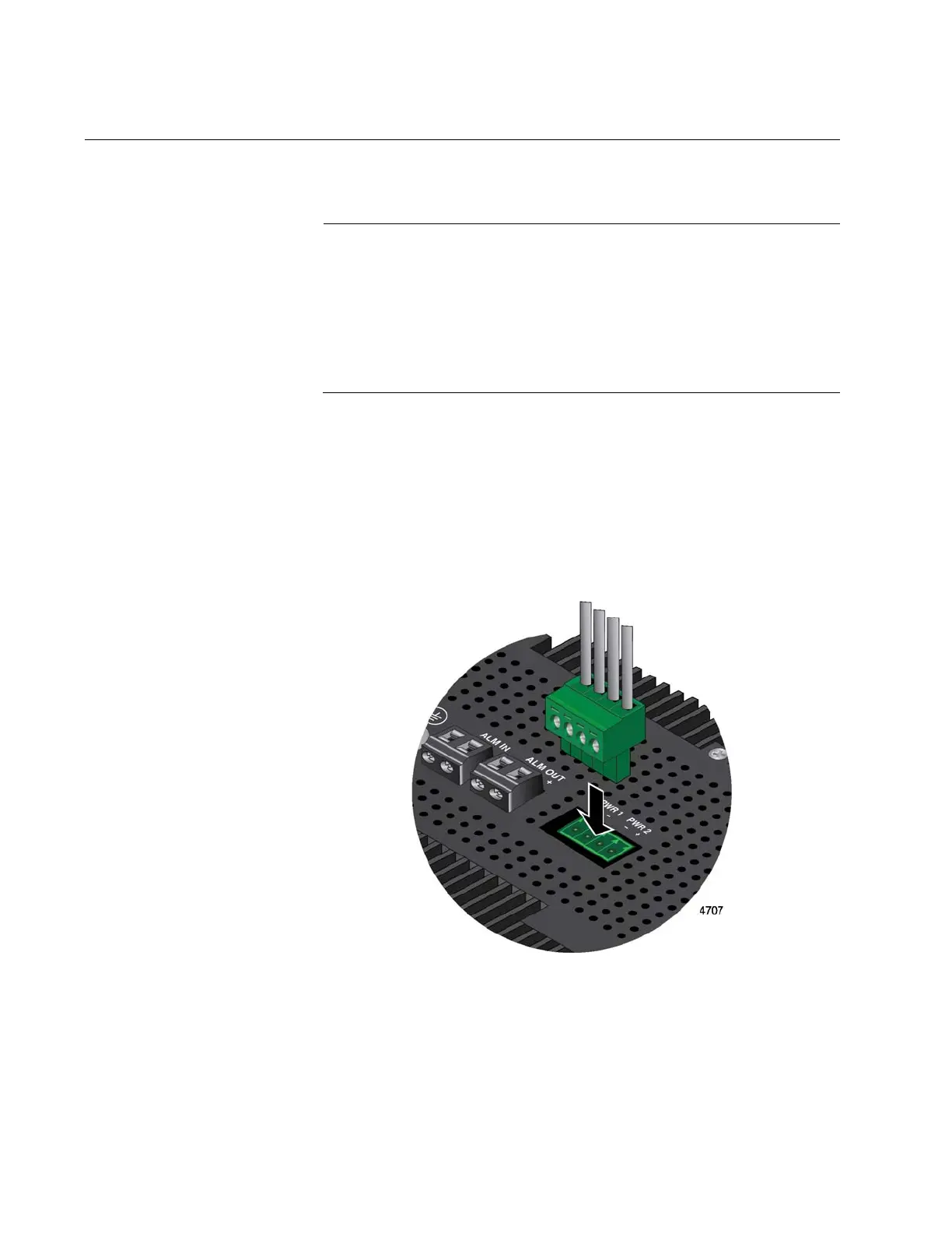
2. Connect the power cable to the PWR 1 - PWR 2 connector on the top
panel. Refer to Figure 51.
Figure 51. Connecting the Power Cable to the PWR 1 - PWR 2 Connector
3. Connect the other end of the power cable to the DC power supply.
Refer to the documentation included with the unit for instructions.
4. Power on the DC power supplies.

 Loading...


