EasyManuals Logo

Allied Telesis IE340 Series Installation Guide

Allied Telesis IE340 Series
136 pages
To Next Page IconTo Next Page
To Previous Page IconTo Previous Page
Page #70 background imageLoading...
Page #70 background image
IE340 Series Installation Guide
70
Installing the Switch on a DIN Rail
The switch comes with a DIN rail bracket pre-installed on the back panel.
The bracket is compatible with DIN 35 x 7.5mm rails. Figure 17 shows the
switch installed on a DIN rail.
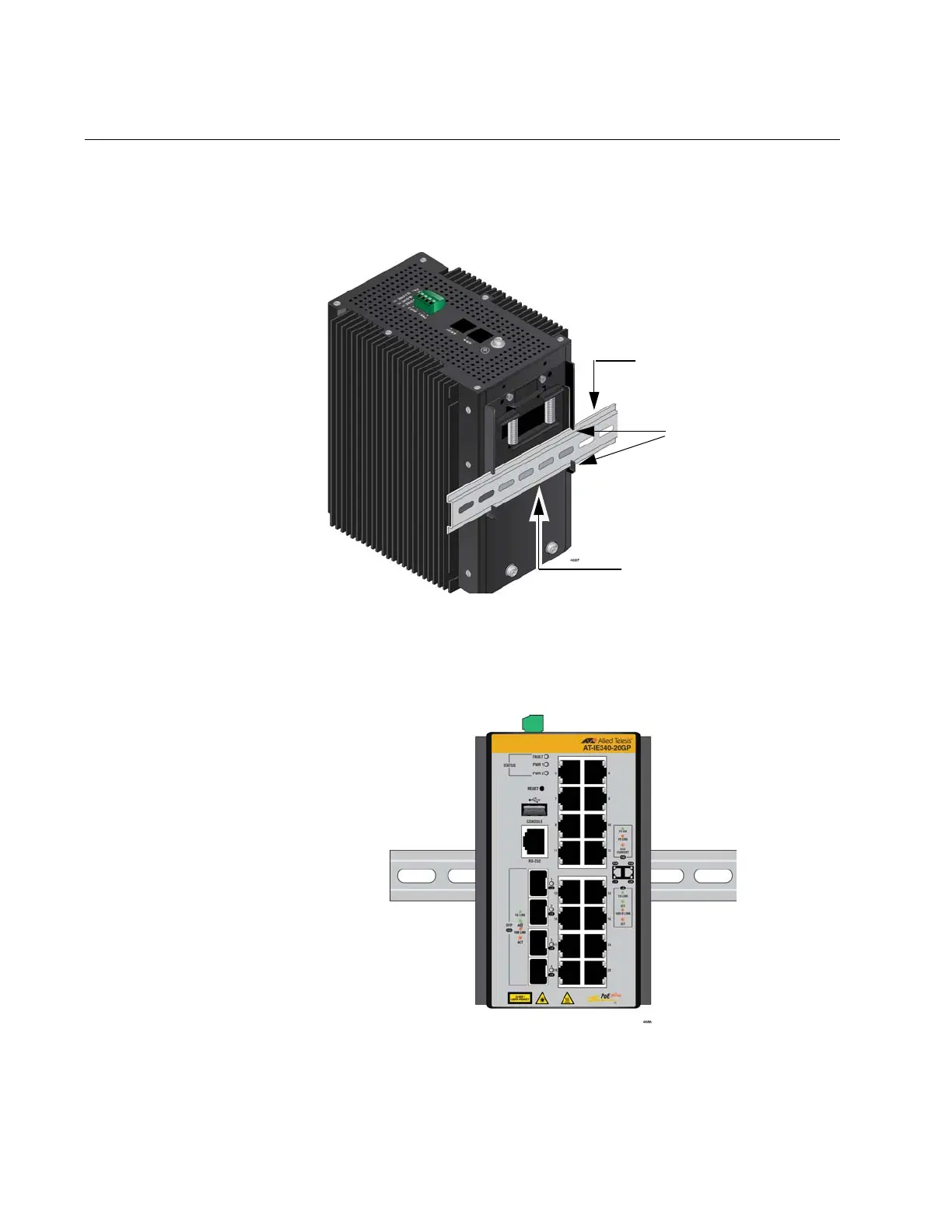
Figure 17. The Switch Installed on a DIN Rail
Figure 18 shows the proper orientation of the switch on a DIN rail. Do not
install the switch horizontally or upside-down.
Figure 18. Orientation of the Switch on a DIN Rail
Top edge of DIN rail
Slots in DIN rail
bracket
Bottom edge of DIN rail

Table of Contents

Other manuals for Allied Telesis IE340 Series

Questions and Answers:

Question and Answer IconNeed help?

Do you have a question about the Allied Telesis IE340 Series and is the answer not in the manual?

Allied Telesis IE340 Series Specifications

General IconGeneral
BrandAllied Telesis
ModelIE340 Series
CategorySwitch
LanguageEnglish

Related product manuals