Chapter 3: Installing the Switch
81
Figure 27. Marking the Locations of the Bracket Holes on a Concrete Wall
5. Place the switch on a table or desk.
6. Use a drill and 1/4” carbide drill bit to pre-drill the four holes you
marked in step 3. Please review the following guidelines:
Prior to drilling, set the drill to hammer and rotation mode. The
modes break up the concrete and clean out the hole.
Allied Telesis recommends cleaning out the holes with a brush or
compressed air.
7. Insert four anchors (not provided) into the holes.
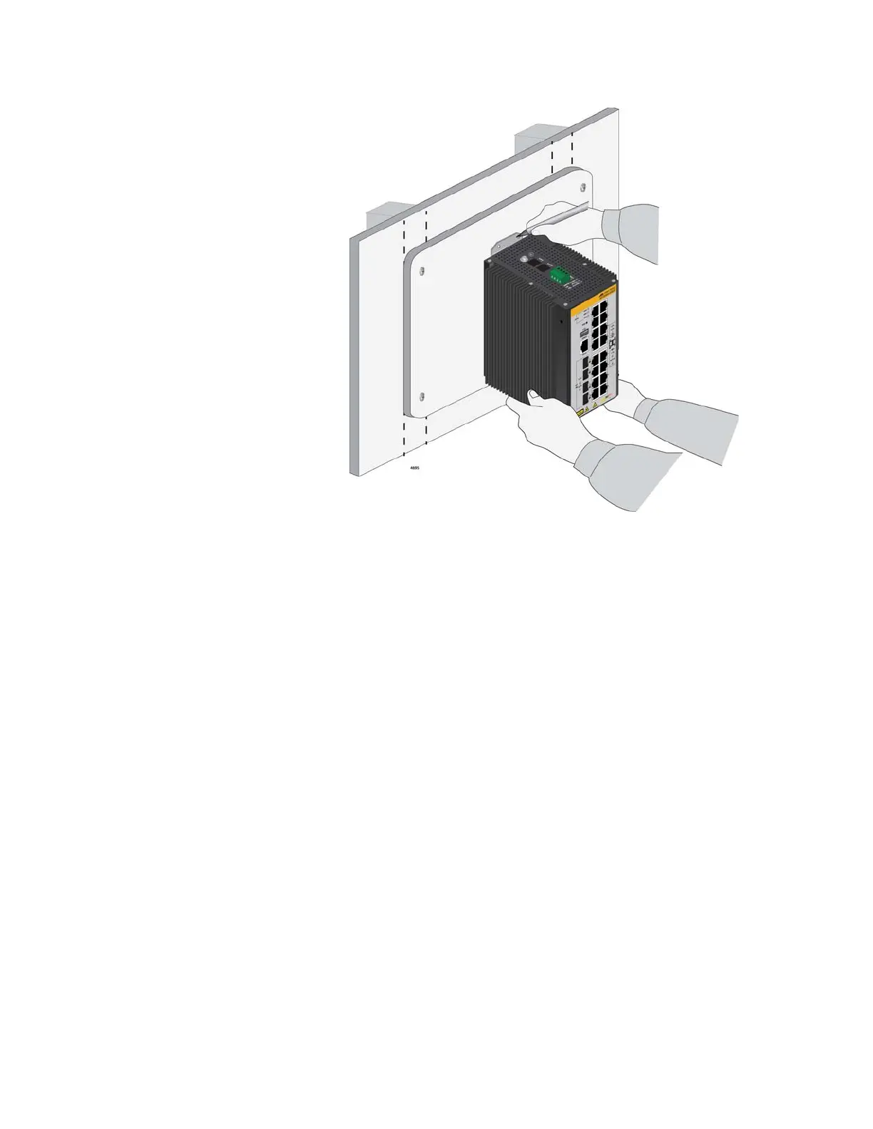
8. Have another person hold the switch at the selected wall location while
you secure it with four screws (not provided). Refer to Figure 28 on
page 82.

 Loading...


