IE340 Series Installation Guide
104
Preparing the DC Power Cables
You can power the switch with either one or two DC power supplies. For
power supply specifications, refer to “Power Supplies” on page 49.
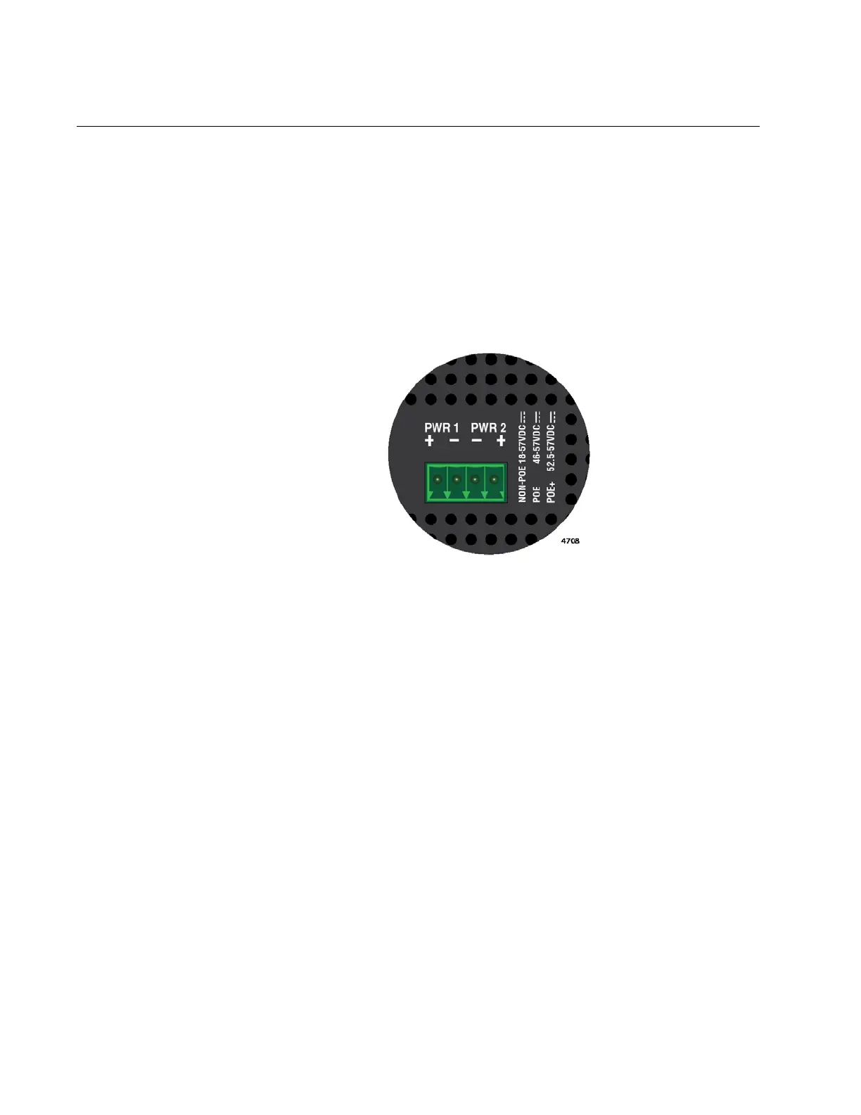
Power supplies are connected to the 4-wire, DC power connector on the
top panel of the switch. Figure 45 shows the DC connector on the
IE340-20GP switch as an example. A power supply is connected to the
switch with two wires, one positive (+) and one negative (-). If you are
installing only one power supply to the switch, you may connect it to either
the PWR 1 or PWR 2 connector.
Figure 45. Pin Signals Legends for the PWR 1 and PWR 2 Connectors
Here are the materials and tools needed to build the DC power cables:
18 AWG stranded wires. Do not use wire heavier than 16 AWG.
2-wire connectors to connect the power cables to the AC/DC
rectifiers or UPS units.
#1 flat-head screwdriver
Wire insulation stripper
To build DC power cables for the unit, perform the following procedure:
1. Strip 6.5mm (0.25 in.) of insulation from the ends of the stranded
power wires with a wire insulator stripper. Refer to Figure 46 on page
105.

 Loading...


