IE340 Series Installation Guide
22
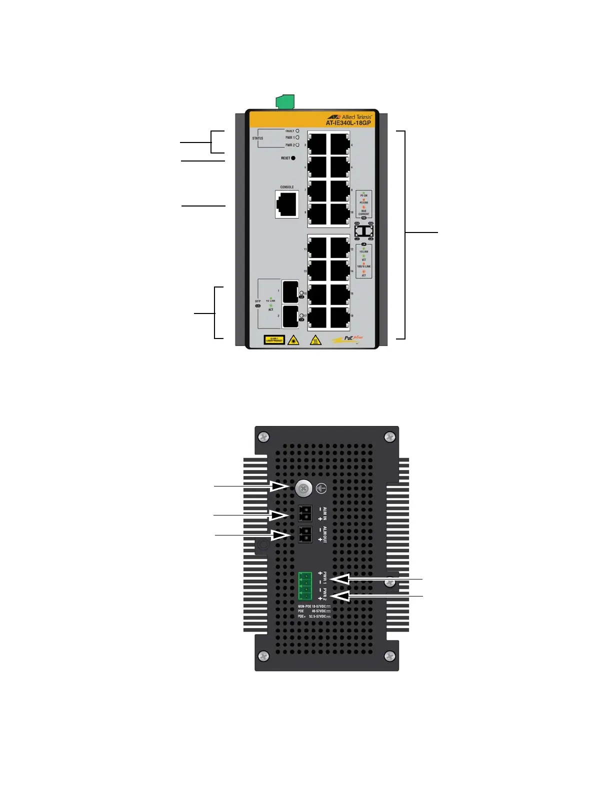
IE340L-18GP The front panel of the IE340L-18GP switch is shown in Figure 4.
Figure 4. Front Panel of the IE340L-18GP Switch
Top Panels Figure 5 identifies the components on the top panels of the IE340-12GP,
IE340-20GP, and IE340L-18GP switches.
Figure 5. Top Panel of the IE340-12GP, IE340-20GP, and IE340L-18GP
Switches
10/100/1000Base-T
twisted pair ports
Slots for
1000Base-X SFP
transceivers
Console
management
port
Status LEDs
Reset button
PWR 2 DC
power connector
PWR 1 DC
power connector
Alarm In connector
Alarm Out connector
Grounding screw

 Loading...


