IE340 Series Installation Guide
132
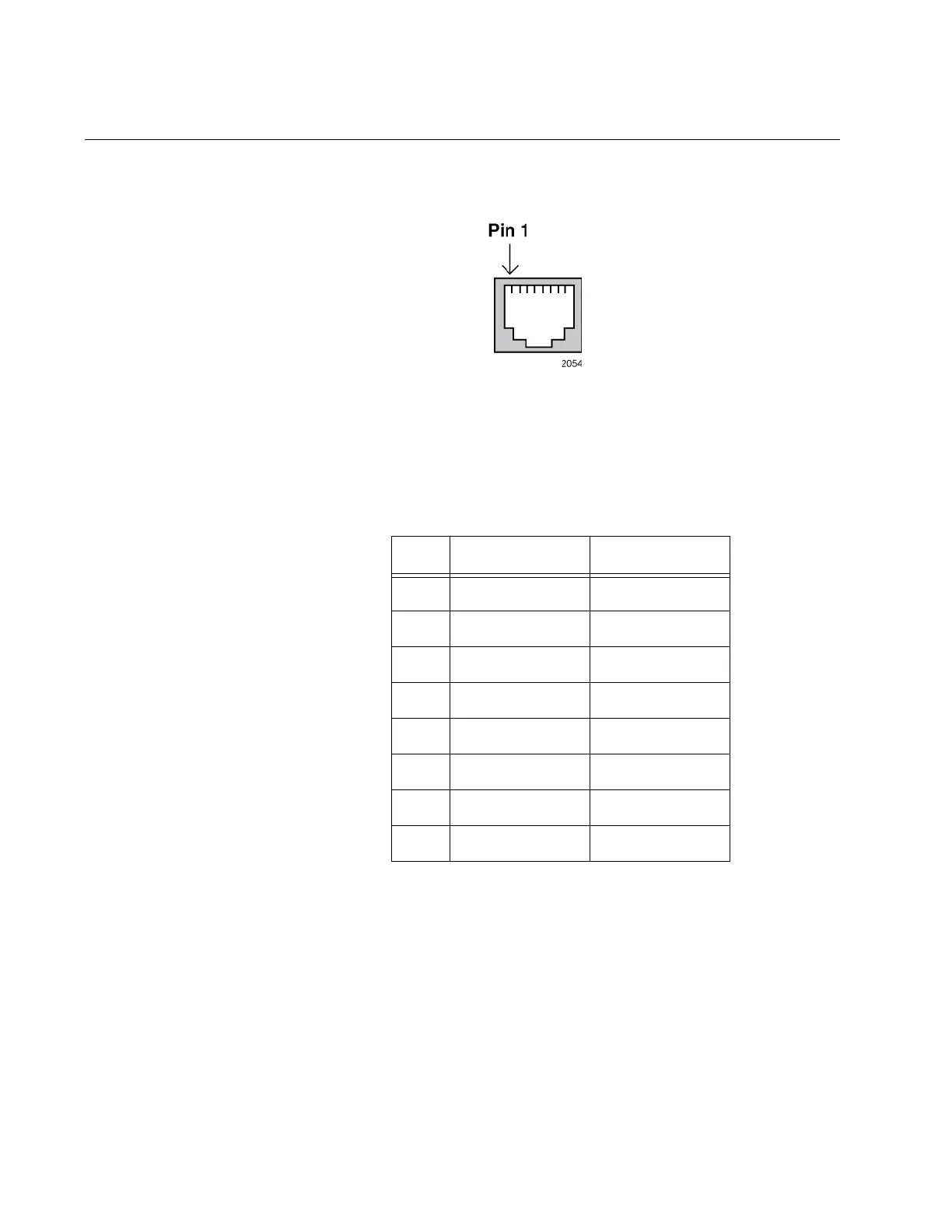
RJ-45 Twisted Pair Port Pinouts
Figure 55 identifies pin 1 on an RJ-45 twisted pair port.
Figure 55. RJ-45 Port Pin Layout (Front View)
Table 23 lists the pin signals for a port when it is operating at 10 or 100
Mbps.
Table 23. Pin Signals for 10 and 100 Mbps
Pin MDI Signal MDI-X Signal
1TX+ RX+
2TX- RX-
3RX+ TX+
4 Not used Not used
5 Not used Not used
6RX- TX-
7 Not used Not used
8 Not used Not used

 Loading...


