EasyManuals Logo

Allied Telesis IE340 Series Installation Guide

Allied Telesis IE340 Series
136 pages
To Next Page IconTo Next Page
To Previous Page IconTo Previous Page
Page #72 background imageLoading...
Page #72 background image
IE340 Series Installation Guide
72
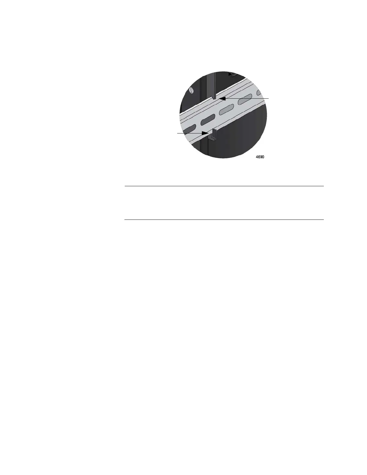
4. Visually inspect the bracket to verify that the DIN rail is now fitted into
the top and bottom slots. Refer to Figure 21.
Figure 21. Verifying the DIN Rail Installation
Note
Allied Telesis recommends installing DIN rail end clamps to the
sides of the switch to prevent damage or network traffic loss from
vibration or shock. End clamps are not available from Allied Telesis.
5. Go to Chapter 4, “Cabling the Ports” on page 87.
Top slot
Bottom slot

Table of Contents

Other manuals for Allied Telesis IE340 Series

Questions and Answers:

Question and Answer IconNeed help?

Do you have a question about the Allied Telesis IE340 Series and is the answer not in the manual?

Allied Telesis IE340 Series Specifications

General IconGeneral
BrandAllied Telesis
ModelIE340 Series
CategorySwitch
LanguageEnglish

Related product manuals