IE340 Series Installation Guide
96
Connecting the Grounding Wire
Here are the guidelines for the grounding wire:
The wire should be minimum #16 AWG solid wire.
The wire length should be as short as possible.
Continuity from the grounding screw to the earth ground must be
less than 0.05 ohms.
If a terminal is used, it should be double crimped.
This equipment must be earthed. The ground screw on the unit must
be connected to a properly earthed bonding point. E120
To connect the grounding wire with bare wire, perform the following
procedure:
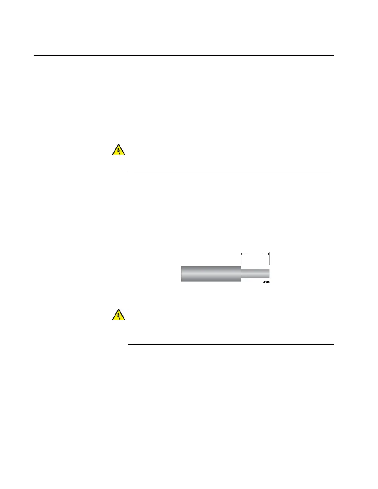
1. Strip 2.54cm (1.0 in.) of insulation from the end of the solid grounding
wire with a wire insulator stripper. Refer to Figure 34.
Figure 34. Stripping the Grounding Wire
Do not strip more than the recommended amount of wire. Stripping
more than the recommended amount can create a safety hazard by
leaving exposed wire on the terminal block after installation. E10
2. Loosen the grounding screw several turns with a #2 Phillips-head
screwdriver. Refer to Figure 35 on page 97.

 Loading...


